Quantcast
Channel: Amplifiers forum - Recent Threads
Viewing all 18754 articles
Browse latest View live

electret mic amplification using TL071 op amp

$
0
0

Hello everybody,

I have a 2-wire electret microphone ( Panasonic wm-62 ), and I want to amplify the signal by about 100 or even 1000 ( the signal is a few mV ) and send the output to an ADC.

I also have a TL071 op amp.

The frequency range which I'm covering is 1Hz - 5000Hz ( I need to keep the information in the low frequencies, not reject them ).

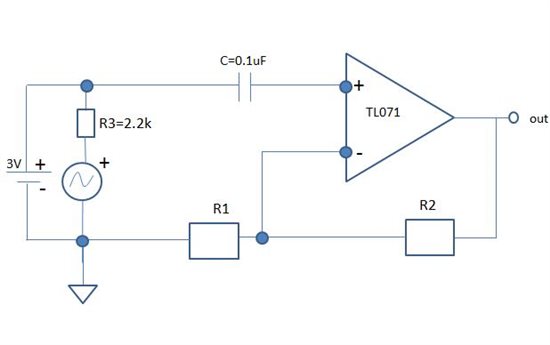
The mic is powered by a battery through a 2.2k resistor, and the output of the mic is AC coupled with a 0.1uF capacitor.

I have 2 questions :

1.How should I hook up the circuit from mic to op amp?

Should I use just the classic non-inverting scheme ( picture above ) or should I add resistors and caps in order to bias the op amp somehow?

The input impedance of this op amp is 10^12 ohms ( from the datasheet ), so the cuttoff frequency of the RC HPF that is formed at the input of the amp is extremely low, which is good for me.

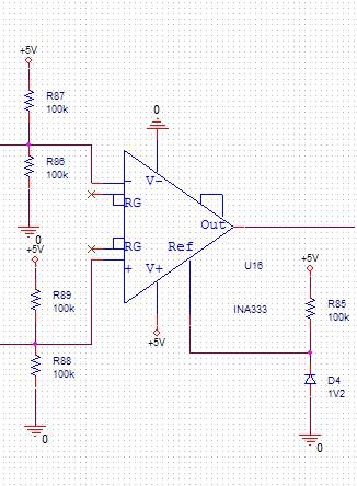
2. Does the application needs the use of an instrumentation amp? or should an op amp suffice?

Thank you,

David.


PGA280 SPI timing.

$
0
0

Hi.

I have been unable to find much information on the SPI timing of the PGA280. 

I have found only two statements in the datasheet.  first is max SPIclk is 10MHz, and data is latched when SPI goes low.

Where can I find information about setup and hold time on the data in, and delay on data out. I there any requirement regarding the CS on delay or similar.

Regards Martin 

INA826 destroyed with 30V Differential?

$
0
0

I hope someone can give me some idea of how I managed to destroy an INA826 with only a 30V differential (smoke came out).  Even If I managed to short circuit something, the spec sheet seems to indicate that it can handle much higher voltages.  I've checked the schematic and probed the board and I've got Vs- hooked to ground, Vs+ hooked to 30V with a 100nF cap to ground and a voltage of around 5 to 15 V going to IN- and around 15V into IN+ and a 51K resistor across the reference.  The board assembler made a mistake and forgot to place all of the components and so the board went through a second reflow, but I don't believe that should have caused any problems.  Even if I leave open the possibility of a short circuit between two of the pins due to bad assembly, can anyone suggest a scenario which would result in frying the chip?  I'm stumped as to why this would happen unless the chip had previous damage that caused an internal short. 

Any advice would be much appreciated.

is there a LMP2014MT spice model?

$
0
0

Hi

I Could not find a spice model for the LMP2014MT opamp. Is there a spice model for evaluation?

Thanks

Jonathan

I want to amplify a low frequency and low amplitude signal and am facing the problem of noise and offset.

$
0
0

I am currently working on a project which involves preamplification and filtering of EMG signals which are small in amplitude (MICRO TO FEW MILLIVOLTS) and are of very low frequency about 50-150Hz. I need help deciding the op-amps to use for the amplification and deal with minimum offset ( ideally maintainable in microvolts).

I would appreciate opinion about selection and circuit design for the same.

Thank you.

100mV level shifting noise observed on INA126

$
0
0


 The gain of the INA126 op amp is set to 460V/V and I am getting a 100mV noise on the output.  Is this a common issue with the INA126 or is the gain so high that the noise is being amplified?  

   In the attached oscilloscope image Channel 1 (Yellow) is being subtracted from Channel 2 (Blue) which is illustrated by the MATH waveform (Red). Channel 3 is the output of the INA126.

Op Amp "Automotive Grade"

$
0
0

My next project is to develop a circuit for an automotive MAF sensor to sense mass airflow using RTD/Thermistors on a Wheatstone bridge, the voltage output from the bridge need to be amplified using an Op Amp.

Could you tell me please, what Op Amp would you recommend for this project? “Automotive Grade” (I can use Dual or Quad)

Note: I'm sorry if I'm not providing detailed specs info, but I don't want you to base your response on my specs, I want you to respond based on your experience/knowledge.  However, please let me know if you need detailed info. THANK YOU.

(Example image, not actual circuit)


Thank you in advance for your inputs.

Josh 

ACF2101 Switched Integrator, HOLD pin not functioning in TINA simulation

$
0
0

Hi there,

 
I hope someone can help me. I'm running some simulations with TINA using the SPICE model for the ACF2101 switched Integrator from the TI website. So far I've been able to get the circuit to integrate the input current and to switch the output on and off using the select port.
 
 
The problems I'm having are that toggling the HOLD switch does not seem to have any effect on the output. I would expect the output to remain more or less stable (capture and hold behaviour) when the hold pin is toggled however the signal is unaffected in either case. I have tried every combination of the RESET, SELECT and HOLD pins however none seems to work.
 
 
A bit of background might be interesting and/or helpful. I'm trying to design a circuit to measure the light transmitted through a medium. The idea is to have a transmitting led in on one side and have it pulse. The sensing LED is placed on the other side of the medium and a circuit will integrate the signal it receives. After a LED on period the signal from the sensing LED will be held and a second integrator will be used to measure the signal when de signal LED is off. The final output signal will be the difference between the LED on and LED off signal. I think the ACF2101 would be ideal for this measurement.
 
 
I have attached a ZIP file containing following files:
 
1) A figure with the TINA schematic I use.
2) A plot of the values of interest from a transient analysis. This also shows all the combinations of the RESET, SELECT and HOLD pin I tried.
3) The TINA schematic file.
 
 
Any insight into why the HOLD pin is not functioning will be greatly appreciated.
 
 
Regards,
 

AC amplification problem - coupling capacitor isn't blocking DC from electret mic - using TL071

$
0
0

Hello everyone,

My circuit is the following simple electret mic + TL071 op amp:

My goal is to amplify a signal from an electret microphone capsule and feed it into an ADC ( NI 6008 USB ). The bandwidth of the AC information is 1Hz - 5Hz aprox, so I have a HPF at the input of the op amp with HPF cuttoff = 0.0339Hz,  and an LPF active filter inside the op amp with LPF cuttoff = 3978.9Hz.

As you can see, the output impedance of the mic is about 10kohms and the input impedance of the non inverting amplifier is the DC bias resistor R3=100k, so I have a decent voltage coupling here.

The 3V battery is for the electret mic and the voltage goas through the Rsource resistor = 10kohms.

The problem is the following:

When my source signal is a signal generator ( with the Rsource resistor and the 3V battery removed of course ), everything works great, and the output DC offset is extremely low, which is great.

But when I connect the mic, with Rsource = 2.2kohm, I measure a significant DC voltage at the input of the op amp - about 0.7 volts!

I tried to change the Rsource resistor to the one you see in the circuit diagram, and the DC voltage at the input reduces significally - to about 0.015 volts. But still - it is there.

I also notice something strange - every time the mic is sensing some signal - like me clapping my hands or something like that, the DC voltage at the input drops to 0 Volts, but then it is slowly rising to the value I initialy measured ( 0.015 Volts ). Of cource the voltage at the output is amplified and the DC voltage at the output is 11 times greater  ( V_os_input*Gain).

I have no idea why this is happening. Why isn't the DC blocking capacitor blocking the DC voltage from reaching the input terminal of the op amp? And why as I aplly some sort of sound pressure, the circuit behaves normally? I'm extremely confused here.

Thank you,

David.

INA333 problem. Output goes to zero when i bias input.

$
0
0

I hope you guys can help me with a problem.Please see attached picture of current test setup:

I'm currently testing a INA333 working with single supply (+5VDC). I am using a voltage reference diode on the reference pin together with a 1kOHM resistor whih gives ~1,2VDC.

On the input i have made two voltage dividers pull up the DC level. When i use 100kOHM resistors the output voltage goes to zero. When i remove the two ground resistors the output goes to the correct 1,2V. When i use 1kOHM resistors the problem seems to be corrected. This is not an option for me because of the nature of my measuring circuit before the INA333 which consists of a coil and a capacitor in parallel (resonance circuit). If i use a low resistor value my Q value falls drasticly and i cannot use the system.

Hope someone can explain the bahaviour im seeing. When using the circuit above i measure identical voltages on the input pins so i really can't make sense of whats going on inside the IC.

Amplifier parameters Bias current Offset current and Offset Voltage

$
0
0

What is the meaning of Bias current  Offset current and Offset Voltage?

How does the parameters impact application when using amplifier in Noninverting Operational amplifier and Inverting Operational amplifier.

INA118 SNR Deterioration of the Instrumentation Amplifier

$
0
0

Hi,

We have obtained one question from our customers.
Our customers will use the INA118 as AD Driver for the ADS7263.
Although we think that the SNR will change in relation to cut-off frequency, gain settings, etc.,
we would like to calculate the SNR of this device.
Could you please tell us how to calculate or SNR values that you calculated or or how to calculate by using the TINA-TI,
or send us the application notes as soon as possible?

Best Regards,
Kato

suitable op-amp for right leg driver

$
0
0

Hi, I simulate an ECG machine it is work very well but whenI did it in real test it doesn't work very well i think my major problem is in right leg driver circuit. my schematic is like this picture but I used lmc660 instead of opa333, when right leg driver circuit is connected the output is full of noise but when i bypass it and just use 2.5volt aright to right leg the output is better. my question is which parameter is important for selecting suitable op-amp for right leg drive. Sincerely yours, Siyavash.


(Please visit the site to view this file)

ADS1278EVM-PDK / ADC PRO

$
0
0

Duh question answers:   Windows 7.  Working internet connection.  Have the EVM.  Have downloaded software three times - adcpro-laucher-1.0.exe.  We do not own a copy of labview.  EVM is connected to power.  EVM is connected to USB through a cable that - by the way - wasn't provided with the EVM.  Really?  Charge $150 and stiff me for a $2 cable?

I run the program.  It tells me ADC Pro isn't installed.  Only option - a button that says get ADC Pro.  Isn't ADC Pro what I just installed?  It is 140 Meg - sheesh - what else would we have downloaded?

I click the darn button.  After a few seconds I get the message that I don't have internet.  Bovine excretion.  I have internet.  I am typing this message to the forum over the internet.

I ignore, I get the same message again.  I hit continue with limited functionality, I get into an endless cycle if installation.  A what's new section, installed plug-ins section that never changes, and scrolling squares that says intitializin.  It has been intializing for 30 minutes.  I've done this several times.  Always the same.  

Congratulations - I just wasted $150 on an EVM I cannot use because the software is a piece of junk.

How to select OP-AMP


How to change the low level voltage

$
0
0

Hi All,

I have a square wave signal generated by the FPGA, which frequence is 500MHz,the High level is 3.3V and Low level is 0V.

I want to change the Low Level voltage between 0V~3V without changing the frequency,High level voltage and rise time of the square wave signal.

the figure is a sketch.1.6V is an example voltage.

Could you give me a recommendation to solve my problems encountered.

Best regards.

Thanks

Penn

Oscillation on buffer output

$
0
0

Hello guys,

I'm designing an analog circuit where I have only a single ended power supply but need to have symmetrical power for some Op. Amps. (LMP2234). To do so, I'm using a voltage reference of +1.25V as an offset votlage for those amps., while they are being powered by a voltage that ranges from 2.5V to 5V and GND. In the worst case, I have a range of +-1.25V (ideally, Rail-to-Rail), with respect to the offset voltage +VOS = 1.25V (to GND). The schematic below illustrates the circuit:

The problem is that the output of this buffer amp. is oscillating (1.25V +- 100mV peak-peak, f = 100kHz).

I have already tried to replace the short between pins 1 and 2 by adding resistance (47R, 1K, 10K) but it didn't improve the output (in fact, using a 10K resistor, the noise increased).

Any thoughts? 

Thanks in advance,

André.

XTR115, XTR116 capacitance on Vref and Vreg

$
0
0

I developed a sensor product using XTR116, several hundreds of which are operating in the field. However, we have had some reports of the output (4-20mA signal) inexplicably getting "stuck".  Interrupting and re-connecting  power ( current loop ) clears the problem, temporarily at least.  I have not been able to reproduce this problem in the lab but I do know it has happened in field installations which should not have had a problem.

When I designed this product, the data sheet (SBOS124 Jan 2000) made no mention of capacitance on Vref causing instability, but now I see a revised data sheet (SBOS124A Nov 2003) which has Figure 5 (which is not in SBOS124) showing compensation networks for capacitance on Vref (I assume Chf ,10pF to 0.5uF, between Vref and Iret is what's being compensated). 

My design has a 0.01uF X7R ceramic cap between Vref and Iret - Can this cause instability?  If so, what would be the effects I could see?  (I use Vref to power and act as reference for a TI DAC7512, my design can't tolerate much capacitance since it's intrinsically safe but I wanted SOME bypassing on my DAC supply/reference) .  Neither data sheet spec's capacitance limits, or requirements, or effects for Vref.   Is that what Fig 5 is doing?  Telling us that Vref can't tolerate capacitance above 10pF? (which is basically any capacitance).   If 0.01uF CAN cause instability, I will likely remove it.  It is strange to have no capacitance spec for Vref (even if it is ZERO), since it is common practice to put capacitance across voltage references.

My next question is Vreg. Again, no spec regarding capacitance. Does Vreg require capacitance (to Iret) for stability? Will capacitance enhance Vreg stability? My design currently has a 0.01uF X7R between Vreg and Iret. Is this enough?  Should I increase it to 0.1uF?  Here again, the data sheet offers no mention of capacitance at the output of the linear voltage regulator.  That's odd. 

I would greatly appreciate some help from someone knowledgeable these two specific issues (capacitance on Vref and capacitance on Vreg).  Thanks.

Counterfeit LM358A? Package does not match datasheet dimensions

$
0
0

I am doing a competitive analysis of a consumer phone accessory and came across an 8-pin leaded IC with the marking "32 TI, M6P". The Part Marking search (http://www.ti.com/general/docs/partmarking/partmarkinglookup.tsp?startPosition=0&navigationId=0&templateId=0&siteFlag=0&keyword=m6p&searchType=partmark) shows that it could be LM358A, but the pin pitch doesn't match the datasheet drawing.

I also checked out the Semiconductor Package info page and there are no TI packages with these body dimensions, pin pitch, and number of pins: http://www.ti.com/sc/docs/psheets/pitch/pitch.html

Body dimensions (excluding leads) are 2.9mm x 3.0mm. Pin pitch is 0.5mm. 8 pin leaded package.

The layout and application suggest the part IS an op-amp, but I can't seem to connect the dots. Please advise - perhaps the National package data is not fully entered into the public IC dimensions page that I am referencing?

Thanks!

Big leakage current in INA226

$
0
0

Hi, I have a trouble about INA226 in my design.

I used a lowside shunt resistor, and VIN+ was connected to power supply(3.32V) directly. A 6.8k resistor was connected between VIN- and ground.

The multimeter measured voltage drop across (VIN-, GND) is 1.62V.

My question is:

as VIN- is pulled down to GND by 6.8k resistor and VIN- input impedance is high, why isn't VIN- pulled close to GND?? How comes the 1.62V? Does leakage current as high as 1.62/6.8k = 238uA really flow out of VIN-?

Viewing all 18754 articles
Browse latest View live


<script src="https://jsc.adskeeper.com/r/s/rssing.com.1596347.js" async> </script>