↧
Need Thermal Resistance Theta JC
↧
OPA211 Opamp as Comparator
Hello,
For my application I need to use a OPA211 as a comparator. Unfortunately I cannot use a 'real' comparator. After reading Analog Devices AN-849 Using Op Amps as Comparators and knowing the possible problems of using a opamp as a comparator I am trying to be very careful with the design. ( I ordered the part and I will to some testing in the bench).
The circuit below is just for reference, as the values are not defined.
Input signal Vg is a 100 kHz to 300 kHz (almost) square wave with 700 mV amplitude.
R1 and R2 bias the AC coupled input to mid 5V rail.
R4 and R3 set the comp reference to mid 5V rail.
R8 and R7 add a little bit of hysteresis to the comparator.
R5 and R6 form a voltage divider to interface to 3V3 logic ( microcontroller)

What parameters should I analyze to evaluate the behavior of this circuit?
There is any recommendation on additional circuit to be added to improve its behavior?
Thank you all and kind regards,
Alexandre Martins
↧
↧
ADS1246 for Strain gauge bridge.
Hello,
I need to implement a Full Strain Gauge Bridge sensor with minimum BW of 40Hz. I am considering using the ADS1246 with a 5V Analog Supply generated by a TPS7A49 and reference in ratiometric mode. Is there any pitfall i should take in consideration. As the ADS1246 is suposed to be used in temperature sensors i might be missing something. The best solution would be ADS1230 but the cornet frequency of 11hz is too low. I will probably be using some CM0 microcontroller with 3.3V power. Finally, any advice on using or not a common mode input filter, or maybe just a capacitor between both inputs (as recommended in the slyp163.pdf presentation)
Regards,).
↧
How to calculate maximum usable value for pull-up resistor on op-amp (or in-amp) input?
How can I calculate the maximum value an input pull-up (or pull-down) resistor can be, to detect a lead-off condition for ECG? A pull-up resistor is used to pull the input high if the electrode becomes disconnected from the patient. 10MOhms is often used, but this greatly reduces the input impedance of the circuit, and the source impedance is normally 100-300kOhms (with mandatory patient protection resistors). It would be much better to use 100MOhms or even 1GOhm, but how can I determine the max value without using trial and error on a whole batch of amps. Is it directly proportional to the input bias current of the op-amp or in-amp, or the input impedance, or any other info from the datasheet?
The op-amps I am looking at in particular are OPA4316 and OPA4377, but I would like to know how to calculate it for any amp.
Thanks.
↧
LVDT Conditioner
Hello guys,
We have lots of industrial applications that use LVDT transducers to measure displacement, usually in microns.
We are considering start developing conditioners for such equipments.
The technical specs of one of this transducers is this:
Sensitivity: 7.38 mV/(Vmm)
Setting 1:10
Amplifier input load: 2 kOhm Input resistance, ± 0.1%
Supply voltage: 3.0 V ±0.5%RMS
Drive frequency: 13.0 kHz ±5%
Coil scheme: Halfbridge, TESA® compatible
Can you guys point me to a component that we can start our development? The end result shoud be a precision amplifier/conditioner that could translate this kind of signal and output it as 0..10VDC or 4..20mA with a sample rate equal or higher than 200Hz? The precision we expect, converting the signal, should be lower than 1 micron.
Thanks.
↧
↧
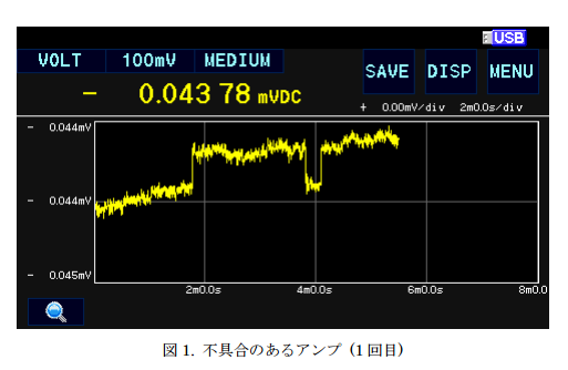
OPA140 output drift
Hi, folks
Our customer mentioned that the OPA140's output drift with source-follower usage.
The schematic and wavefowm was below.
In this case, observed 0.5uV unexpected (also temporary) drift when source-follower.
Also some other device shows 0.2uV, but some devices have not seen.
Could you let us know the reason why this temporary offset occurs?

↧
Query on equivalent part of BUF634 in either 4 channel or 2 channel
Dear Sir
I am using a video buffer BUF634 in between video output and ADC input.
In my application i am getting 4 video outputs, for each output before giving to ADC input i am using BUF634 for each video channel.
In between to reduce board size i tried to use OPA2690 and even OPA2691, it didnot work for me as BUF634 worked. Then i revert back to again 4 numbers of BUF634.
My application needs very low noise components. Can you please suggest a component in place of BUF634, which is multichannel but electrically it should behave the same way as BUF634. Preference is 4 channel then only two channel video buffer.
Kindly suggest.
↧
TLV3401, TLV3402 - Output behavior at power up
Hi Team,
Please allow me to ask you the output behavior of TLV340x during power up. We sometime see output dip on OUT pin during power up. Is this normal operation ? Why would this happen ? Power on reset ?
I apologize asking you the operation under recommended minimum VCC, however, I would be grateful for your help.
Best Regards,
Kawai
↧
Need Thermal Resistance Theta JC
Dears;
Could you please tell me the Thermal data about three amp; Junction to Case/Junction to Lead Resistance (Theta JC) of OP-Amps :OPA4340EA(8VSSOP); INA2132UA(14 SOIC), OPA4130UA(14 SOIC). Very appreciated.
Best regards
Kailyn
↧
↧
xtr116 problem
in my circuit i am using two xtr 116 to generate 2 4-20ma.from that from one xtr116 i use voltage to power up my controller and other circuit and second one is only for 4-20ma generation.as in second xtr i am not using its voltage i unconnected its iret pin and only join 200k resistor between pin 1 & 2. so there should be 2ma current in that loop.but in multimeter 4.5ma current is showing. i made directly pcb so here i attach rough schematic drawn on paper .i don know what is the problem
the out put of voltage follower ic for second xtr116(in which facing proble is 0v)so only 200k resister is in picture
↧
LM119 Input voltage range
Honeywell looking to drive the input of an LM119 with +/-15V signal powered off of single 5V supply. The LM119 datasheet seems to indicate that the max input voltage is VDD (5V in this case). However, there is a question regarding, if this voltage limit is really based on limiting some current flowing into the input pins or some other limitation. They have a 10k resistor in series with inputs and this design is an older one, so we assumed that the resistors were put there for protection.
Is there an issue if they applied a 15V signal to the LM119 input (assume other input is at 2.5V), but with a 10k resistor in series?
Shawn
↧
Using the LMP91000 in Analog only. How to implement filters?
↧
LMP91000 and Arduino Problem!!!
Im facing these problems ... Kindly help me with your opinions and suggestions, and correct me.
1) Im working with Arduino and LMP91000 aiming to use it for electrochemical purposes. How do i give inputs to achieve cyclic voltammetry?
This is what i tried.
If i start with setup of bias=20% of internal Vref (2.5v) and internal_zero= 20% of Vref (2.5v) , with negative sign , and continue the same for varying bias percentages (negative 18%, 16%, 14% ..... 0%...positive 1%, 2% ..... 20% ... positive 18% , 16% ..... 0% ....... negative 1% , 2% .... 20%), i would get the voltages in steps of 0.05v resolution when calculated theoritically and i wld get 0.1v resolution when measured across WE and RE using multimeter. why is it so?
RTIA = 7K and R_Load=10 Mode= Three_Lead Amperometry
/* Wire.beginTransmission (LMP91000_Slave_Address);
Wire.write(REFCN);
Wire.write(Internal_Vref | Internal_Zero_20 | Bias_Negative | Bias_20_Percent);
Wire.endTransmission();
Wire.requestFrom(LMP91000_Slave_Address,1);
delay(1000); */
2) The multimeter voltages which im getting in steps of 0.1v is not correctly displayed in hyperterminal !!! why?
3) Another problem which im facing is, the Vout pin shows 1v irrespective of bias which im giving. Output is not varying. whats wrong?
4) How do i check whether my LMP91000 is working or not?
It would be lot of help if someone answers these . Thank you.
↧
↧
XTR105 affect with ground capacitance
Hi,
We are using XTR101AP for RTD to 4-20mA converter for more then 15 years. Now we need to replace the old XTR101 IC with new XTR105. The 2 wire RTD is mounted inside a flexible metal tube & the distance will be approximatly 2 meters. Both XTR101& new XTR105 PCBs are powered with +24V loop supply.
Both the PCBs reading are identical with fixed resistor & RTD calibrator. While connecting the RTD sensor(with metal tube) & leave it to the ground, the current output increasing about 0.5mA. If we placed the sensor setup on a wooden table, the reading are not changed. If we touch the metal tube with hand, the reading are changed. Non of the metal parts are in contact with sensor leads. I have isolated the power supply with an isolation transformer, but the problem remains same.
I just add a 3 turn through hole ferrite bead at both end of input supply & loop current output. Now the XTR101 output is get stabilized & found only 0.02mA variation & this is negligible in my case. But the problem remains same even if I connect the ferrite bead to the XTR105 PCB as mentioned above. I hope this is happening because of the earth capacitange. If I connect a RTD without the metal cover, this is working fine. Please give advice to clear the problem.
Regards
Udhay
↧
MPY634
HELLO THIS IS HOT
I NEED TO NO IF THE PIN OUT IN THE DRAWING IS CORRECT
WHAT I NEED TO NO IS THAT IF I HAVE A SINE WAVE FEF. ON THE X (+) INPUT AND THE NEG. INPUT TO GROUND .
VOUT OF THE PART IS TIED TO Z1 AND Z2 WILL BE MY SUMMING NODE FOR CURRENT SENSE SIGNAL.
NOW I HAVE FROM THE OUTPUT OF THE INVERTER A SENSE NETWORK AND A POT THAT I WILL USE TO ADJ. THE OUTPUT VOLTAGE THIS VOLTAGE WILL GO INTO THE Y(-) INPUT AND THE (+) IS GOING TO GROUND .
NOW WHAT I NEED TO HAPPEN IS
AS THE FEEDBACK SIGNAL ON THE Y(-) INPUT BECOMES GREATER THAN THE SINE REF THE OUTPUT SINEWAVE WILL START TO DECREASE
AND AS I ADJ ARE TURN R3 ON THE DRAWING I CAN MOVE THE SET OUTPUT VOLTAGE UP AND DOWN AND ONCE I HAVE THE OUTPUT CORRECT I START TO LOAD THE OUTPUT OF THE INVERTER AND YOU SHOULD SEE THE OUTPUT FROM THE MPY634 INCREASES TO TRY AND MATCH THE SIGNAL OF THE FEEDBACK TO IT MAINTANS REGULATION
LET ME NO ARE UPDATE THE DRAWING AND SEND IT BACK TO ME AND I WILL MAKE THE CHANGES HERE.................
SO THE MAIN IDEA HERE IS THE REF SIGNAL ON THE X INPUT IS CONSTANT IN AMPLTD. SO I NEED TOHAVE THE SAME AT THE OUTPUT OF THE MPY634 AND WHEN I APPLY A FEEDBACK SIGNAL THE V OUT SIGNAL SHOULD DECREASE AS MY FEED BACK SENSE SIGNAL BECOMES GREATER THAN THE REF SIGNAL
GET BACK PLEASE ASAP
THIS IS HOT
↧
PGA280 PSRR/CMRR -40dB/decade
I am planning to use PGA280 as an input amplifier for a data logger. To design an appropriate input filte I were thinking about the acheavable CMR-ratio over frequency. Figure 14. on page 10 of the data sheets shows a linear degration of the CMRR from starting from somewhere over 100Hz to 100kHz. This is normal. What supprises me is the steep decay of -40dB/decade. To my knowledge the decay is caused by some sort of parasitcs. But this normally cause a decay of -20dB/decade. As the power supply rejection ratio (Figure 13.) shows the same strange -40dB/decade decay I wonder if these graphs are correct - indeed I hope they are not! But if so can anybody explaine where this unusual -40dB/decade slope comes from. Finally I just want to mention that the advertised CMRR of 140dB is also not reproduced in the graph.
Thanks!
↧
Using the LOG114 to detect negative current (electron flow)
Hi,
I'm trying to use the LOG114 to measure negative currents in the range of 100p to 10uA.
First a description of the application: We are using a microchannel plate (MCP) to collect ions. The output of the MCP is a stream of electrons on the anode that need to be measured (See picture for basic orientation)
I'm trying to use the LOG114 in place of the ammeter for measuring this electron current. To achieve this objective, I tried connecting the anode to the LOG114 through the current inverter circuit as seen in Fig 7 of the datasheet . See TINA simulation circuit below: 

While the simulation shows a perfect transfer function as it is expected at the output, on actual testing, the results are erratic and do not follow a log function with jumps in the voltage output.
When tested individually, the current inversion section and the log-amp section work as expected. Even when connected together, if there is an ammeter placed between inversion circuit out and I1 of the LOG114, the ammeter reads the correct positive current. However, the output voltage of the log-amp doesn't represent this current. The laboratory tests are being conducted with a precision current source in place of the MCP.
Any ideas on how to proceed at this stage?
Thanks,
Vidur
↧
↧
composite opamp amplifier with BUF634 need helps

Hello, everyone. New participant here.
I recently read an idea about composite opamp circuit and nested feedback, and figured out the about circuit.
(the drawing missing a resistor connecting front opamp positive to ground, 200Kohm)
But when I put it into test, the output is very unstable and distorted.
Even with grounded input there will be DC output.
The only combination worked is using OPA2111 for both opamp.
I wonder if this one theoretically works and if there is room of improvement.
(The idea of this circuit is to gain the benefit of using BUF634 while using an low distortion opamp to push the distortion of BUF634 lower by unity gain.
and the front opamp is used as amplifier at gain=4. My idea is, if use only one opamp with BUF634 to amplify, distortion of BUF634 will just partial feedback to the opamp for correction so the total distortion will be higher.)
↧
Signal conditioning for geophone input
I need to pass a signal from a geophone (essentially a moving coil in a magnetic field with ac output) through an amplifier to a processor whose A/D inputs are 3.3 volts tolerant. As far as I'm aware, there are no zener diodes I could place back to back in front of any op amp between the geophone and the A/D circuitry which can limit the input to the op amp (or instrumentation amp) to 3.3 volts max (I would be adding 1.6 volts dc offset at the op amp stage).
So my first question is: what kind of clipping circuit could I assemble to clip the input the to the amplifier to say, +/- 3.3 volts, if any ?
I have also thought about introducing an INA 121 with a single-sided 3.3 volt supply as the input stage (again with a 1.6V offset), relying (if I am correct) on its high input voltage protection features to clip its output to the ADC to the 0 to 3.3 volt range in the presence of possible input voltages exceeding +/- 3.3 volts. I don't know if this would work, so I'd appreciate feedback on whether this is another viable option.
Finally, if I do use the instrumentation amplifier as the input to the ADC circuitry, given the nature of the geophone output, would I need to provide a high resistance path to ground for both INA inputs as input protection for the instrumentation amplifier ?
I hope I haven't muddled this question too much !
Thanks !
↧
Is the θJA(150℃/W) of OPA354(5 Pins package SOT-23) right ?
Hello
The OPA354 datasheet p.5 of the following URL
http://www.tij.co.jp/general/jp/docs/lit/getliterature.tsp?genericPartNumber=opa354&fileType=pdf
Thermal Resistance(θJA) of SOT23-5 (and MSOP-8) are listed with 150℃/W.
I saw datasheet p.4 of OPA354-Q1.
The OPA354-Q1 datasheet p.4 of the following URL
http://www.tij.co.jp/general/jp/docs/lit/getliterature.tsp?genericPartNumber=opa354a-q1&fileType=pdf
Thermal Resistance(θJA) of DBV(5 Pins) is listed with 216.3℃/W.
I think that Thermal Resistance(θJA) of OPA354(SOT-23 package) is 216.3℃/W.
Best regards,
Keishi,Nishijima
Japan PIC
↧