Dear sir
we are using analog switch but when the logic at 0 we get a output voltage about 0.450V but it should be zero.so what could be possible reaons. the part no of -sn74lv4053a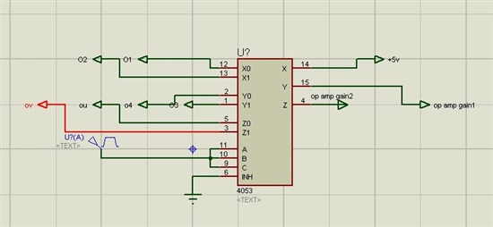
Dear sir
we are using analog switch but when the logic at 0 we get a output voltage about 0.450V but it should be zero.so what could be possible reaons. the part no of -sn74lv4053a
Hi all
There are the following questions about OPA541AP.
1. There is no simulation model with the current limiting function of OPA541AP.
How can the simulation model be obtained?
2. For example, connecting OPA541AP's outout to six-piece parallel.
To what ohm should it set Rcl in the case of setting output current to 10A?
3. From a calculation result to "Rcl=0.3ohm" its desired current was not reached,
However, when Rcl was "0.1 ohm", output current became about 10A.
Is there such any example?
Best regards
Hisa Kobayashi
I'm not sure by calculating the Gerrtot:
Gerrtot[%]=Gerr[%]+R2/Rin[?]
My example:
Gerrtot=0,05+140/28000
Gerrtot=0,05+0,005=0,1% ???
Or
Gerrtot=0,05+0,005*100%=0,05%+0,5%=0,55% ???
Whats right?
Thanks for your reply!
Hello, I am looking for a high precision amplifier to measure nanoampere currents. I am planning to use MSP430, I wonder which amplifier is convenient for this application. Is there an application note ? Thank you !!!
Is there a drop-in replacement for OPA128SM?
hi all,
i need help in my circuit design.
currently i am designing a transimpedance to detect pico amp to micro amp. (10pA-1uA)
the gain required for this varies a lot from 1M ohm to 10G ohm
for the 1st stage of amplifier i am using the OPA128 which did quite a good job in getting 20-30pA reading
but the problem i am facing is that my ADC can only read a range of reading from 1mV to 10V
therefore, i need to varies the gain to reduce the noise read the current signal.
for having a large range i need to change the gain resistor value to minimize the noise(EMI/RF) and to set the output voltage to a readable range.
is there any ic/or thing that can help me do a gain selector like what have been done in this patient?
My OPA448 circuit is functioning correctly with the exception of the E/S pin. Pulling this pin low, correctly, shuts down the amplifier. If an excessive load is applied, the device temperature rises and the device shuts itself down - as expected. However, when the device is in self shutdown it does not take the E/S pin low to indicate shutdown mode.
I need to know when the device is in shutdown mode. The data-sheet clearly states that it is possible to monitor E/S, via a CMOS logic device. What is going wrong? All help most welcome. Thank you.
Hi,
I'm in the need of a current buffer/follower with unity gain. I have a low output resistance(250Ω) current signal, and I want to convert it into a high output resistance(anything higher than 250Ω) current signal. I have searched over TI's website, and the forum, but I couldn't find a current buffer, or any other product with this functionality. Here is my application:
I'm trying to design a circuit which will read a 4-20mA signal from a sensor, but it also will give an analogue output of the same 4-20mA signal, without any output resistance loss.
The only way I know to read a 4-20mA signal is running it through a series resistor, but in that way I will be cutting from the output resistance of my analogue output. I don't want that, because most of time people use a 250Ω resistor to read the 4-20mA signal. Therefore some sensors are designed to give max 250Ω output resistance. So if I use a 10Ω resistor to read the signal from the sensor, I will be leaving my analogue output only 240Ω output resistance.
I don't want that disadvantage, therefore I need a current buffer with a precise unity gain, so that I can read the 4-20mA signal, and output it with a high output resistance(at least 250Ω). I would appreciate any help.
Best Regards
Omer
This is to request SPICE (H, PSPICE, OR Spectre) model parameters of NPN, PNP, JFET transistors that are used to build a Lm118
A list of sample model parameters of PNP are follows:
.model vp10tk33 pnp + level = 1.0000e+00 subs = 1.0000e+00 + is = is_vp10tk bf = bf_vp10tk nf = 9.9500e-01 + br = 1.7300e-01 nr = 1.0010e+00 ise = 1.6228e-17 + ne = 1.3110e+00 isc = 1.7050e-15 nc = 1.0170e+00 + vaf = 4.7300e+02 var = 1.9620e+01 ikf = 3.9811e-03 + ikr = 3.4674e-03 nkf = 7.9500e-01 rb = 1.0000e+02 + rbm = 7.0930e+00 irb = 5.0119e-05 re = 5.9320e+00 + rc = 2.5950e+01 cje = cje_vp10tk vje = 4.2160e-01 + mje = 3.5418e-01 fc = 5.0000e-01 cjc = cjc_vp10tk + vjc = 5.0000e-01 mjc = 2.0880e-01 xcjc = 1.0000e+00 + tlev = 0.0000e+00 tlevc = 1.0000e+00 xtb = 1.4600e+00 + eg = 1.1700e+00 xti = 2.8700e+00 tikf1 = -5.6000e-03
Look forward to hearing from you with parameters.
Keun
Hello ,
I use the OPA551 and the OPA552 on my trial board. I have OPA551 in non inverting mode for a gain =2. The supply voltage =+/-25V and the input signal =+/-4V. If the input frequency is lower than 20KHz, my output signal = 2*input signa=+/-8V. But when my input frequency is greater than 20KHz my output signal is greater than +/-10V. I read some explanations about a gain lower than 5 but i didn't understand. Is this possible to have more explanations to choose the capacitance to avoid oscillations.
Thank you for your reading
Malela a student from France
Hi,
I am using a PGA113 as an amplifier for an analog measurement by a microcontroller ADC.
The input signal is a fixed 1Hz sine wave. On the low side of the input range, the singal fed into the amp is about 2.5mVpp.
With the gain at 5x, the output signal is shightly shifted in time.
The measurement was performed directly at the input and output of the amplifier. There are no capacitances connected directly to the amplifier and both input and output have 10k in series. A oscilloscope screenshot is attached, which shows the phenomemon.

The screenshot shows:
-a reference signal (C1, Z1, yellow)
-input of the ampifier (C3, Z3, blue)
-output of the amplifier (C4, Z4, green)
The deltaX between the vertical markers is 31.17ms. The markers are placed at the tops of the sines, by hand.
Does anyone have an idea why the time shift occurs?
Could you please provide me with the STEP model file "m14a.stp" for the SOIC14 case of TLC742BI. There is a dead link on the product page as well as on the workbench CAD/CAE Synbols database for this file.
Recently, I use the PGA309 for my application. And I use the microcontroller to control the PGA309 through IIC .And I can read/write the PGA309 register successfully.But the Vout is still wrong. This makes me carzy!!! Here is my step:
1、Tied the TEST PIN to a microcontroller IO port, and before the registers' configuration I pull down the test pin.
2、 After the configuration set the test pin is high and enable the Vout.
The circuit diagram refer to the User‘s guide F3-5. The signal is 0.9125V but my Vout is just 25mV. I don't kown what is wrong with it.
so I ask for help here.
Reference circuit: http://www.ti.com/lit/an/sboa025/sboa025.pdf

Hi,
I have the above circuit operating on 24V Battery. The only difference is that the load cell has a 3m long shielded cable.
Whenever there is any Mains operated switching in the vicinity, there is fluctuation of output current. Probing further, noise is observed on the power rails. Adding a filter before the INA114 and decoupling the power rails doesn't seem to help.
There is no earthing available as the unit is mounted on a mobile platform having rubber wheels. The load cell shield is terminated to DC Ground near the amplifier.
Can anyone help solve this problem?
Thanks,
JayantD
Hi,
I have a self-design Radial Disk Resonator. Now I would like to measure its Resonant Frequency. As my calculation, Disk Resonator has resonant frequency at 8MHz. I would like to add transresistance Amplifier that linear stable from 5MHz to 40Mz to detect the resonant frequency phenomena. Please help me choose one Amplifier and circuit diagram connection to my Disk Resonator. I am using Network analyzer E5071C to detect the resonant frequency.
I am really need your help, my major is mechanical so I have very little knowledge on electronics device.
Thank you very much!

According to the TI website, one of the features of this chip is the antilog computation. However, I don't see that it's possible when I go to the datasheet. Are there any application circuits to obtain an exponential output from this chip?
Does anyone know if an INA133 can drive a 1 mfd capacitor?
Hello, trying to help my 12 year old son,
Regarding LM331 wired exactly to figure 18 Simple Frequency to voltage Converter 10 kHz Full Scale (10volts).
What components should we change to convert 5 Hz to 4 volts?
TI document SNOSBI2B –JUNE 1999–REVISED MARCH 2013
Thank-you for your help.
Is it possible to use LM331 as a frequency to voltage converter in the range of 40kHz - 60kHz? I need a resolution of say 0.5kHz, preferably smaller. Ie, I need to be able to tell if the frequency is 44.5kHz or 44kHz.
In the datasheet of LM331, there is only an example circuit for 0-10kHz F2V. I have made this circuit, and it works fine up to 10kHz, but above this frequency, it does not work.
Could anyone explain to me what needs to be altered to make a F2V, 100kHz circuit using a LM331 work? If you have a schematic, please upload it.


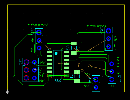
I am using IC IVC102 as a transimpedance amplifier. In the figure given on top is the switching signals given to S1 & S2 through microcontroller atmega 32.
First two figures show the switching signals. Integration time is 200 ms.Switching signal are exactly as given in figure 3 given in datasheet. Supply voltage given is +/-
13V. Input given is 5V through a resistor of 1 giga ohms hence a current of 5 nA. Connections have been done as given for switched input measurement techique. Third
figure shows the output
IC. Blue line is the output. The whole circuit is put into a box as shown in last figure above. 4th figure shows the pcb connections for IC IVC102.
As can be seen in 3rd figure the output of IC is not linearly rising but is constant at 2V.
Given below is pcb design for the IC IVC102. Why am I observing such behavior from the IC?