Quantcast
Channel: Amplifiers forum - Recent Threads
Viewing all 19361 articles
Browse latest View live

Multi-Cal-PGA309 system

$
0
0
Hi, my name is Daeyoun Yun.
 
I have any questions(PGA309EVM-USB and Multi-Cal-PGA309).
 
First, look at the PGA309EVM-USB evaluation module, I know to make a calibration using the PGA-test board. 
 
If, without using thd test board, what should I do wiring connection when using the real-world pressure sensor(PGA309 built-in)? 
 
Second, always needs RS232 communication of the DMM when the calibration by using the Multi-Cal-PGA309 (I used the Multi-Cal-System = sofrtware)? 
 
Do not have to be calibrated via a wire connection without using an RS232 communication? 
 
Finally the DMM script that is attached to the software, do I want to be a used to modified? 
 
Whenused withoutchanging theDMM script,the calibrationis not performed. 
 
For example,it was confirmedthat the outputvalueof theactualchange, butVoutshown inPC monitordid not change.
 
I look forward to your reply.
 
Thank you.
LMC6442 schematic transistor design

$
0
0

Hi. We're students from Argentina. We're trying to develop a contactless ECG electrode. For this application, it would be useful for us to obtain information about the schematics transistor design of the LMC6442. Is there any chance you can send us a basic sketch of said schematics?

Thanks in advance.

Alberto and Matías

XTR116 Vref and Vreg accuracy calculations

$
0
0

My question is regarding the Vref and Vreg accuracy calculations. When calculating the voltage accuracy vs temperature and supply voltage, is it  ppm or mV over delta temperature and supply voltage or is it ppm or mV over absolute temperature and supply voltage

PSpice model for LMV431

$
0
0

Someone have the PSpice model for LMV431?

OPA378 odd behavior

$
0
0

I am using an OPA378 as a buffer on a reference.  It is configured as a unity gain buffer, with an RC filter (1MEG series, 15nF shunt) before the noninverting input, and followed by a connection to pins 3 and 4 (high terminals) of a TPL0102-100 (digital pot).  The low terminals are tied to ground so this looks like a 50K load.

V+ of the OPA378 is just shy of 3.3V.  V- is at ground (measured).  The input to the RC filter should be 500mV but in circuit is 478mV.  The NI input of the OPA378 is at 436mV so there is a 42mV drop across the 1MEG resistor (well beyond what the bias current would normally cause).  The output of the OPA378 is at 497.6mV even though the output is tied to the inverting input...no gain resistors. 

I have looked with a scope and all of the waveforms are solid DC...no oscillations.

If I remove the input RC filter and inject a DC signal from a reference directly into the NI input, the amplifier works perfectly.  I have used RC filters on the NI input of opamps before without a problem.  The application required a very low-noise reference so I would prefer not to remove the RC filters. I'm well within the CM spec for the part.

Any idea as to what is causing the problem?

Tim

AFE031 programming

$
0
0

I’m trying to program the AFE031 Analog Frontend with a F28069 Microcontroller. Unfortunately there is some information missing about SPI programming in the AFE031 datasheet.

Maybe somebody has already  experience in programming the AFE031?

It is written in the datasheet that a host SPI frame consists of a R/W bit, a 6-bit register address, and eight data bits.

First question: Is the following assumption correct?

R/W bit =1 performs Write Operation

R/W bit = 0 performs Read Operation

Second question: Each frame contains of 8 data bits. To write date to a AFE031 register do I have to transmit the MSB or the LSB first?

OPA340 input offset voltage calculations

$
0
0

Hi,

What is the meaning of Offset voltage over temperature ? shown below.

OP-amp TLV2781

$
0
0

Hi everyone:

I want to design a voltage amplifier. I'm using the low consumption TLV2781 and a single supply op-amp desing found in page 6 ofthe following file:

http://www.eng.yale.edu/ee-labs/morse/compo/sloa058.pdf

I've used resistors so that the gain is around 5. The input is coming from a signal generator and the power is coming from a DC source. Now, the problem is that the signal is distorted. The distortionis not harmonic or clipping, I believe. The distortion is like linearizing the curvature of a sine signal.

Can anyone help me?! I actually used two designs and they all fail. BTW, how much distortion is allowed in an amplifier?! is it the problem with TLV2781 ?!

Thanks all,


Op amp gain vs. operating temperature

$
0
0

I have an application for which I need a quad op amp that has almost perfectly flat gain across its operating temperature.  Unfortunately very few data sheets contain this information.  My operating conditions are 3.3V single side supply, gain bandwidth product does not need to be very high ( 1 MHz + ).  The best part I could find in my search is OPA4354AIPWT, however my tests with this part are still showing more gain drift with operating temperature than I had hoped.  I made sure to use +/- 10 ppm/C resistors in the op amp network, currently configured as a non-inverting amplifier.  If anyone has personal experience or knowledge of an op amp product line that has excellent gain vs. temperature performance, please let me know.

Regards,

Matthew Dzikowski

[Consultation] How are the input impedances of OpAmp meatured?

$
0
0

Hi guys,

OpAmp has differential input impedance(Rd) and common(Rc) input impedance. Well, I think Rd=4*Rc. However, specifications in datasheet of opa2356 indicates that Rd=Rc. 

So, how are the input impedances of OpAmp meatured? 

OPA1642/OPA1612

$
0
0

I use these amplifiers for pro audio. I also refurbish large format recording consoles. Currently, I require opamps in the DIP package. I would like to see these parts offered in a DIP package to replace the OPA2134PA. I would use several thousand for one job, IF they were made available in the DIP package. As such, I'm limited to using the National LME series, those are made in the DIP package. I really need the fet input parts in a DIP.

Marketing at TI needs to get with the program here. They are missing a large market share by not releasing these parts in a DIP package. Just hobbyists would buy enough to make it worthwhile.

Are you listening, TI?

XTR111 Interface

$
0
0

Hello-

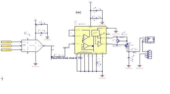
I am designing a 4-20mA current generator with XTR111AIDGQT.  Following is a schematic. The series resistor between DAC and XTR111 is 243 Ohms instead of 10K.

It seems the chip is pretty strieght forward but I do have some issues with it. The DAC is 12 bit so it can set output from 0V to 4V. When I input 0V I observe ~0mA at the poutput but when I switch input to 2 or 4V output switches to 2.15V max.

I will appreciate your responses.


Regards


OPA552/OPA445

$
0
0

Hello, 

I'm Malela .  I use the OPA552 for a amplification board . i got 2 stages: a follower voltage and a non inverter amplifier(gain1.5).

I got a problem on the output of the follower stage: there a oscillations on the output signal when the input signal is a square signal or sinus signal. If i change the opa552 to use an opa445, i have no oscillations, but the output signal on the output follower voltage is attenuated. I would like to know to cut these oscillations if could use a low pass filter( RC). I would like to know too why withe the OPA445 ,the output signal is attenuated because i would like use it to a attenaution board in follower voltage stage and a amplifier stage (* 1/6)

Thank you for your reading

Malela , a student from France

LMP91000

$
0
0

I would like to know the Fit- Rate for LMP91000.

Information about AFE031 S-PVQFN-N48 and package

$
0
0

Hello
         'll do tests on samples sent me TI, the AFE031 and am in the design phase of the PCB. I extracted the physical dimensions of the encapsulated S-PVQFN-N48 Data Sheet (http://www.ti.com/lit/ml/mpqf123e/mpqf123e.pdf) where there is information about separation between pin, dimension etc. but I did not find information about the dimension of pin and pin dissipation.
Is there any more specific data sheet for this package?

Thank you.

best regards


2 Lead dry electrode ECG circuit

$
0
0

Hello TI,

I need a circuit design for a 2 Lead Dry contact electrode ECG system. I am selecting INAMP & OPAMP for the design. Please suggest me a very good working circuit & IC'S. Please I am not preferring ADSXXXX series.

My requirements are as fallows,

1. It is a handheld equipment with battery powered, so the power consumption should be less.

2. The production quantity is 2000 piece/month, so the cost of the chip & circuit should be very less.

3. The circuit should have very good reliability & repeatability.

3. The electrodes contact with thump [dry contact], so the sensitivity should be linear for all type of skins.

Please provide me necessary support to start my project....

Thanks & regards

Udhay

Need some help determining reference value for bridge amplification circuit.

$
0
0

I am using the INA122 to amplify a mV signal from a strain gauge.  My basic circuit works, but it appears that I am falling below the 100 mV minimum input which is causing linearity errors.  This is my spec's.


Vcc = 2.5V single supply

Gain R = 425 ohm

The strain gauge is a 350 ohm 2 mV/V output(0 - 5mV).  My a/d has a range of agnd to 2.5V.  I am probably going to have to bias this as well.


So what I am looking for is how to calculate the appropriate ref voltage to give me a 150mV to 2.3V output.


Thanks in advance.

AFE031 SPI Trouble

$
0
0

  I am trying to interface the AFE031 via SPI to control the DAC. The output is changing as I write to SPI but not as I expect. I suspect that the SPI mode is incorrect, is there a way to tell the AFE031 which mode to expect? I have read the data from a logic analyzer and am quite certain that my SPI signal is sending the proper data. Any other info regarding the AFE031 would be very much appreciated as  I find the datasheet and Analog Front End Design Note to be very brief.


 I have attached my code and would appreciate if you could take a look at it. It is very simple

http://pastebin.com/pjkMQaN4

INA159 input voltage range

$
0
0

The INA159 has a supply voltage range of +1.8V to +5.5V with an input voltage range of up to +17.5V. Does this mean that the amp could be powered by +5V and could be fed, say, a +12V input signal? The fixed gain of 0.2 would yield a +2.4V output, well within the supply range, but it seems unusual for the input of an IA to exceed the supply, especially by so much.

PGA280 SPI timing.

$
0
0

Hi.

I have been unable to find much information on the SPI timing of the PGA280. 

I have found only two statements in the datasheet.  first is max SPIclk is 10MHz, and data is latched when SPI goes low.

Where can I find information about setup and hold time on the data in, and delay on data out. I there any requirement regarding the CS on delay or similar.

Regards Martin 

Viewing all 19361 articles
Browse latest View live


<script src="https://jsc.adskeeper.com/r/s/rssing.com.1596347.js" async> </script>