Quantcast
Channel: Amplifiers forum - Recent Threads
Viewing all 19064 articles
Browse latest View live

Design Support: OPA549 parallel configuration amplifier oscillation

$
0
0

Hello E2E,

I am trying to build an amplifier using OPA549s in parallel configuration. I've attached a schematic. In prototype, I'm having an issue where the amplifier is oscillating when the set point is positive such that the amplifier is sinking >~7A  and when I have more than 10,000pF switched in. This instability is not present when the amplifier is sourcing current and is present even if the load is purely resistive.


This design is an extension of an older design, using only OPA549 amplifiers, that design had a maximum capacity of 7A and was stable over the whole range of feedback capacitors.


Any thoughts of things to check or clarifications I can make?


Thanks

-Pete


Problems with INA122P

$
0
0
Dear Sr. I'm trying to use a INA122P instrumental amplifier with a load cell and a microcontroller, but when I connected everything I obtain values that varies too much. All is connected to 5 Vcd, the amplifier: Pin 1 and 8 are connected with a 180 Ohms resistance Pin 2 and Pin 3 are the outputs of the load cell, Pin 4 and Pin 5 GND, Pin 6 to microcontroller Analogic port, In a LCD I can see the values that the amplifier gives to the micro controller and with 10 bits of resolution my window is 0 to 1024, If I press the load cell it response with a value more greater, but my problem is: the value always oscillates never is the same value although I put the same weight; I try connect 10Kohm resistances to ground to the Pin 2 and Pin 3, .1uF capacitors to pin 2 and pin 3 to ground, I connect a .1uF capacitor to Pin 6 to ground, I Connected a 1 Kohm to Analogic Port and .1uF capacitor to ground and the values always oscillates, What you think is wrong? Thank's

OPA2333 model

$
0
0

Hi,


I'm trying to simulate an EMG circuit. I created my first circuit in TINA using INA333 and OPA2333 and practically implemented the circuit as well. 

Now I'm trying to simulate the same circuit but using a different instrumentation amplifier from AD. From AD, I found the spice model in *cir format, which was easily imported into multisim, as I cannot use TINA for that.

I am having trouble importing the OPA2333 model into multisim. At my university, I do have access to other circuit simulators (albeit not experience in all of them, like Proteus, PSpice etc.) I would really like to import the model into multisim. I tried following some instructions for generally importing models into multisim by creating your own schematic block and manually copy pasting the SPICE code text into it. it doesn't seem to work. In addition, as the OPA2333 is a dual opamp ic, and uses all 8 pins, in the model, it seems the subckt line refers to only 5 pins.


I'd appreciate any help I can get here.

Regards,

Usama

OPA2335 Bypass Capacitors

$
0
0

Hello,

Per product datasheet, in application information: Good layout practice mandates use of a
0.1μF capacitor placed closely across the supply pins. Would the 0.1 uF value
be a minimum or maximum value?


Thanks,

Andrea

How to use the integrated operational amplifier TL0602 voltage two wire circuit

$
0
0

How to use the integrated operational amplifier TL0602 voltage two wire circuit

TLV2372 Input Current Noise Figure Correct?

$
0
0

Hello,

I don't normally look at the specifications at this level but my current project has required me to do so.

I'm looking at the input current noise figure on the data sheet for the TLV2372.  When I compare it to other op amps that we currently use, it has higher figures for the input voltage noise (39 nV vs. 4.5 nV [On 33078]).  I also noticed that the input current noise if _significantly_ lower (if correct)  the TLV2372 reads as 0.6 _f_A, and the other amplifier specification is 0.5 pA.

My belief was that the voltage and current noise would 'track' each other.  The higher the voltage noise, the higher the current noise, but maybe I'm wrong.

Can anyone confirm that this is a typo, or give me some insight as to why the _huge_ difference in current figures when the noise figure is so much better on the other part?

Thank you,

amplifing and filtering small modulation on big voltage

$
0
0

Hi

I have this signal ti is a 100KHz sin signal with amplitude modulation on it.

the amplitude is around 17V and the modulation is around 0.3V is there an amplifier (or circuit+amp) that can cut the amplitude and magnify the modulation so it can translated?

Regards,

I

NEED HELP TO FIND DOCUMENT??

$
0
0

Hi

I'm looking at the document with literature number SNOA839 "A quick sine wave generator", where can i find the on-line excel sheet for calculating the components?

Many thanks 


How do they do it, 1900GHz GBWP?

$
0
0

I found a particular Silicon-based sensor with an integrated opamp pre-amp.  It has a gain of 10G (1E10, 200dB) using a 10G feedback resistor and a 190 Hz bandwidth.  I call that a 1900GHz GBWP (Gain Bandwidth Product).

How do they do that?  I'd like to be able to do it myself, outside of this sensor with the integrated opamp pre-amp.  But I can't find an opamp with anything close to that GBWP.  The highest I find at TI is 18GHz.  The highest I find at Linear (LT) is 10GHz.  And those also have far lower than a 10G open loop gain.

Are they cascading opamps but using a single feedback resistor across both?  This is about low noise, so it has to have a very larger resistor.  Two stages at 100K each won't do the trick.  And I don't find anyexamples of cascaded opamps sharing a feedback resistor.

So, again, does anyone have an idea of how they do this?

I believe the opamp on that sensor might be on the same subtrate as the sensor.  The same company has a small module with include opamp that I'm sure is not on the same substrate.  The detail is hidden, but I believe this thing has a 1E8 (160dB) gain.  Again, the highest open loop gain I've been able to find was under 130dB.  But because this opamp isn't integrated onto the same substrate, I would think I could build my own from available parts.  (And since there's isn't 200dB, I'm guessing they couldn't find off-substrate parts as good as their on-substrate opamp, perhaps.)

This is all about minimizing sensor noise by having a very large low noise first stage pre-amp.

Thanks very much.

opa 381

$
0
0

Hi guy,

i follow ti note to attached with the photo sensor , why is the output voltage is 2.8 v while my dack current is 9nA.

below is my attached. is there any formula to calculated the output voltage.

Minimun width for routes using OPA1632 in audio aplications and power supply

$
0
0

Hi and thanks for reading the question:

I'm designing an aduio system using a PCM4204 ADC. For the buffers needed for this ADC (as it says the datasheet) i'm using OPA1632. My question is if there is a minimun width for the PCB routes for the audio signal across the buffer. I've noticed in the EVM's PCBs of the PCM4204 that the routes in the buffer are wider than the rest..

Another thing that i need to know is if i can power the operational amplifier with +5/-5V instead of +15/-15. I know that the opamp should work (the range is +2/-2 to +18/-18) but i dont know if the performance is affected or not.

I don't know if this is the right place to post this questions, but i would be very grateful if someone can help me...

Thanks very much...

OP AMP OPA 2541

$
0
0

Dear Sir / Madam,

Dear Sir / Madam,

We are using one of your Op Amp OPA 2541. We have  OPA 2541BM which has an operating temperature range of -25⁰ C to +85⁰ C with an absolute maximum ratings of -55⁰ C to +125⁰C.  However,  our application requirements are from -30⁰ C to +55⁰ C. There is no issue on positive temperature, as the requirement is only up to +55⁰ C against the operating temperature of +85⁰ C. However, on the negative side, the requirement is -30⁰ C against the operating temperature of  -25⁰ C. If the device is tested and meets the requirements at -30⁰ C, can we use the device as it falls short only by -5⁰ C and well within the absolute maximum ratings. Request for your advice.

Regards,

Srinvas DV

devulapally_d@ yahoo.com

ts the requirements at -30⁰ C, can we use the device as it falls short only by -5⁰ C and well within the absolute maximum ratings. Request for advices.

Regards,

Srinvas DV

LMP7721 Evaluation board Transimpedance config.

$
0
0

Hi TI,

This is a follow-up question from (http://e2e.ti.com/support/amplifiers/precision_amplifiers/f/14/p/328519/1145207.aspx#1145207) original post.

I have another question regarding the LMP7721 eval. board.

I have changed the original eval. board in to trans-impedance configuration from non-inverting config. My question is, can we use same input bias current test that shows in this video (http://focus.ti.com/general/docs/video/Portal.tsp?langId=en&entryid=0_65zy5r36) for TI config? 


Because, when I tried to measure the input bias current with the same procedure, evaluation board now gives around -1.5V (when input is connected to the ground. When I disconnect it from the ground, it gives near 0V. Is this something wrong with my board?

Your suggestion regarding this will be greatly appreciated.

 Thanks

~Ishara

ISO124 vs AMC1200

$
0
0

Hi,

I need to sense a 600VDC signal on an inverter bus and I am looking at both AMC1200 and ISO124 as options.  The ISO124 is much more expensive and I don't see any benefits to use it over the AMC1200.  Maybe I'm missing something? 

Please Advise.

Thank you very much.

Omer

OPA 365 + FTZ869 as laser driver

$
0
0

I want to use the application of opa 365 to make a driver for laser diode .  and when i saw a nice laser diode driver design, coming from Texas Instruments's  SBEA001 (the "Laser Diode Driver 1") by Neil P. Albaugh ,  i thought it is a good design for laser driver .  but i can not find the exact datasheet for FTZ869 . i think it is wrong in the design and that transistor should be FZT869 . Am i right ?


OPA2333 TINA Simulation not working

$
0
0

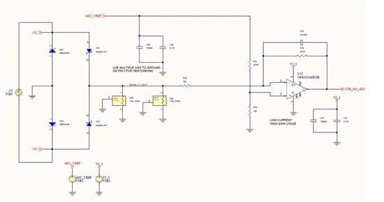
I am facing an issue with TI TINA simulation software. I have OPA2333 on current sensing and amplification circuit and I want to simulate it before implementing the same.

(Please visit the site to view this file)

The below attached excel sheet will give the idea what is expected voltage on the OPA2333 op-amp output. But when I simulate in TINA the output oscillating on 3.3V.

(Please visit the site to view this file)

I have tried with altium designer mixed sim also but altium is giving me timestep too low error when I add op-amp to circuit. Without that it is working ok but no use.Circuit image of altium is attached below.

Please help me  to solve this issue..

AC coupling of Photo-diode to TIA

$
0
0

Hi,

Regarding the DC removal circuit shown in various posts, will it help SNR in an application where a large optical signal is 1% modulated at 100k-200kHz. I can see how the DC-servo can help remove the DC portion, and prevent TIA saturation to the rails, but would it also remove noise at the AM modulation frequency?

Thanks

PGA280 single-ended input, differential output

$
0
0

I just want to make sure my brain is not installed backward today.

I should be able to push a single-ended input into the PGA280, right?  Just connect INN1 to ground and INP1 to my signal.  I see common-mode rejection ratio vs frequency that's above 100dB when below 1kHz.  My need is below 1kHz and a final SNR above 60dB, going in and out of the PGA280.  So it seems to me that any common mode signal leaking through to the output will be much smaller than the SNR of the signal passing through anyway.

I'd also like to use it as a single-ended to differential converter.  My input in fact varies from +Vin to -Vin, relative go GND, and having a dual supply.  So more specifically, I believe one would call it a single-ended bipolar input.  I believe the PGA280, wired with INN1 to GND and INP1 to my +Vin to -Vin signal, will convert that single-ended bipolar input to a differential output, right?

Thanks very much.

the input impedance of OPA2322 when power down

$
0
0

Hi BU team

Would you share me the input impdecnace of OPA2322's Vin+ when power down?

Thanks 

Instrumentation amplifier for high accuracy load cell

$
0
0

Hello,

I have to design an Instrumentation amplifier for a Load cell with a resolution of 0.1 gm and I am going to use a 24 bit ADC at the o/p end of IN amp. please tell me if its better to build an Instrumentation amplifier or buy one for this application and why.

If i can build then,

Is it  better to divide the designing in two parts: difference amplifier( 2nd part) and buffer stage(1st part). But i do not know on which factors should i select the resistor values and the right opamp for each part and how to check the output of each part.

It would be helpfull if someone could give me a step by step process on where to start and what to know for designing an Instrumentation amplifier. I am trying the way of learning by doing. so, please help me

Regards

Viewing all 19064 articles
Browse latest View live


<script src="https://jsc.adskeeper.com/r/s/rssing.com.1596347.js" async> </script>