Pin 2 is set to NC (No Connection). Does that mean that it's not connected internally or that nothing can be connected to it. We want to go through pin 2 with a another signal is that ok?
↧
Pin 2, LOG114
↧
Need help upgrading opamps!
I'm Brandon,
I have a M-audio projectmix 8 channel mixer (http://m-audio.com/products/en_us/ProjectMixIO.html). I have recently taken it apart to see if there are any mods I can do. I found that there are 8x JRC5532 opamps on the XLRs inputs. These I want to replace first. There are JRC4580 opamps on the TRS inputs and 4 JRC4580 opamps on the 4 main speaker outputs. Money being no option, I am looking to replace all opamps with the BEST opamps as far as specs go... highest frequecsy response 20hz-20khz and so forth. I am not an engineer by any means but am very handy with a soldering iron and can follow schematics decently. This mixer cost me $1200, so I just want a drop in chip. I do not want to have to change the circuit at all. However, I will also be replacing the caps with top end caps-I can easily look at the specs on those so.. do not nee help with that. I do not have schematics for the Projectmix, but can provide some photos inside. Any one who can help my e-mail is warsleyer@aol.com.
↧
↧
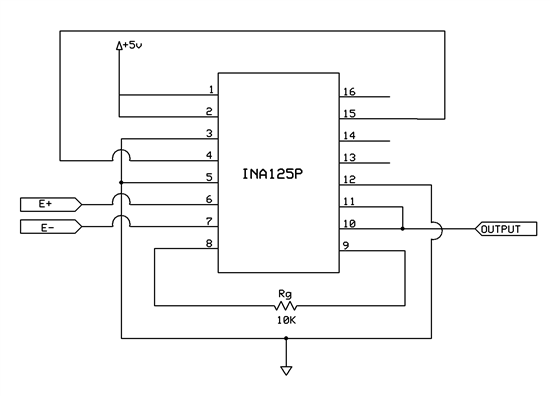
INA125P and Arduino
Dear,
I have a problem while amplifying the signal of a load cell by using a INA125P (integrato)
I am not able to achieve a defined value under a certain limit. Here following some examples:
If a insert the Arduino ADV value read without load =0, the error is spread on all measurements. If I detract it I still experience no detection untill a certain limit.
By using a 200N load cell I get a value (related to the gain set), of about 20 ADC without load, which finally correspond to a initial reading threshold of about 0,7 - 0,8 N.
Normally we use 3000 N load cell. The threshold moves consequently thus preventing low loads detection that yet become significant ( about 10%).
I also cannot perform load cell calibration, as normally it is applied by linking the ADC value to 0 load and the FS to the relevant value. This because 0 value is underneath the threshold.
By resuming, it is like the load cell zero was under the threshold amplifier reading.
So, If I could move the zero value to a slightly higher tension, I should have solved the problem. But I do not know how to get this done.
To simplify:
If I have not load reading under the reading threshold I will never be able to calibrate these.
Let's consider the example of a Kitchen balance that starts to weigh right over the 100 gr. value ( it would not visualize 99 gr, yet it would visualize 101 gr). If I place a 80 gr plate ( but of course I do not know it before...) and then I want to weigh 500 sugar gr, how can I detract the plate weight?
Enclosed Scheme picture
Thanks,
Sergio

↧
multi-PGA309 question
Hello! I'm Daekeon from Autonics.
I have question on multi PGA309 program.,
I use this program to calibrate our pressure sensor but i don't know some sign that is displayed program window.
Here is a picture.
At this picture, What's the meaning theVin_Low , Vin_High" ??
I have known that this sign is a differential input voltage of PGA309 . That's Vin1- Vin2. Is that right?
But, It's not same between displayed value and measure value in person.
When i measured PGA309 Vin voltage at offset state, the value is about 30mV.
but, The displayed value is 5mV.
Please let me know on this question.
↧
pH measurement with TI's INA116
I am trying to implement a pH measuring device with INA116 chip. One of the applications of the chip is pH measurement.
Constrants: pH ranges from +- 430 mV. Max input/output 2 Hz frequency. Gain of 11.5 V/V
PH probe have very high impediance ranging from 100 - 1000 MOhms. So INA116 chip is a good choice.
I have attached a pic of my current ckt.
Problems I am having right now:
1. Noissy signal. On the output signal, I am getting frequency in thousand to mega Hz.
2. The offset voltage is fluctuating from -800 mV to 300 mV or sometimes stable at -400 mV. Now if I place a .10 uF capacitor between inputs the output goes down to -70 mV. Have a offset is a big problem for me as I need 0 mV offset to start with other wise my pH reading screws up. Is there a way to implement auto-zero input offset circuit.
NOTE: with gain set to 11.53 v/v
3. I don't know what type of (LPF @ 2Hz) filter should I implement to at the input and output to block any noise [ without blocking dc input mV signal] from entering my signal and high frequencies. AC-DC power supply do sometimes introduce 60k Hz frequencies too.
↧
↧
PGA309 documentation and documentation in general
Can I make a few suggestions:
Please clean up the dates within the filenanes in the FTP site: ftp://ftp.ti.com/pub/linear_apps/
A fair amount of stuff is missing the year. e.g. PGA308-NEW_MAR9 This is like grandma when she made jam, She labeled them all New. Is this Mar 9, 1901 or 2011?
Some of the PGA30x software is in LabView and no where can it be found (I suggest README) what version of LabView. Labview is very wierd, at least when I used it, where NI always wants you to be current and the latest version sometimes will not convert all previous versions. So, I think, mentioning the version is on order.
The same is true for EXCEL. Mention the version and the options that need to be installed. It was nice that one of the spreadsheets mentions what's needed and how to install on the first page.
I did find a fair number of embedded PDF links not to work in the PGA308 and PGA309 datasheets.
While doing a glance over the documentation, suggested EEPROMS didn't jump at me.
The other thing that did not jump out at me was the suggested method to connect the programmer to one's built circuit and you can;t really disconnect all of the pins of the PGA309/EEPROM.
It looks as if those wanting to do a custom whatever, LABView would probably be the way to go. I know some companies create a DLL which LabVIEW can use and so can any language.
I looked at the scripts used to drive the USB platform and it looks like it could possibly use some enhancements in decoding messages.
Pretty impressive.
↧
information on lm148 opamp
i want to know whether lm148 is available in SOIC package or not??
WHAT IS THE EXACT ALTERNATE PART FOR LM148???
LM148 IS OBSOLETE PART OR NOT???
↧
can I use PGA309 and XTR115 to form a Intrinsically safe explosion-proof pressure sensor?
hello
can I use PGA309 and XTR115 to form a Intrinsically safe explosion-proof pressure sensor? I have known nothing about explosion-proof. could you give me some suggestions?
thank you.
↧
To connect 4-20mA/ 24V sensor output with PIC18F
Respected,
I'm working on wireless connectivity of 4-20mA pressure sensor, in which i need to convert 4-20mA varying o/p current into appropriate variable 0-5 V.
for this RCV420 Current sink is used, but at the time of connectivity some problem arises like DC-DC isolation, RCV420 connection to controller as voltage mismatch.
Please help me to come out from this problems.
↧
↧
NEED INFORMATION- LMC6464BIN/NOPB
Hi Can you please provide the following information for the LMC6464BIN/NOPB Part ?
1. Junction Temperature Max (Tj Max)
2. Typical Power dissipation (Pd typ)
3. Maximum Power dissipation (Pd max)
4. Thermal Resistance Junction to Ambient (Theta JA
5. Thermal Resistance Junction to Board (Theta JB)
6. Thermal Resistance Junction to Case (Theta JC)
7. Weight
↧
INA125P interface with ADC of Microcontroller
Dear SIr / Madam,
I am trying to interface a loadcell with controller's PLC which can read 0 - 10V or 4- 20mA of analog signal.
I tried to interface loadcell with PLC but got failed. After some searching on web i became to know that INA125P helps to interface loadcel with other devices. So i order sample of INA125P to try.Unfortunately the same result repeats here also.
I used the connection same described in starting of datasheet of INA125P. Used Rg =10k and sleep tied up with VCC.
Used power of 5v which is regulated from 7805.
Loadcell details:
Red - V+ : 5VDC
Black - Gnd : Gnd
Green - Signal +
White - Signal -
Operating Volt : 5vdc
Maximum Load :3kg.
when i checked the signal output using multimeter its showing +2.5v for both signal of loadcell without any load on loadcell and not connected to INA125P. but while connected to INA 125P its showing some mv on meter and it varies each poweron time. but not varying output while applying load on load cell.
why it is like this?
Does i did any mistakes in wiring ?
I am trying to get voltage varying output to interface with PLC analog module. Please help to overcome this issue.
Enclose herewith the schematic diagram of INA125P. Find the diagram for more details.
Regards,
Nikhil V V
↧
zero cross detector problem
i have someting like sine wave signal and i want to convert it into square wave signal.is negative supply is recomended for it. i already apply o as vee and 12 volt as vcc but output is not obtained.
↧
ARC protection SM73201
1) customer evaluate SM73201 for arc protection, power on the equipment, that have instant voltage spiking, that similar with arc , so trigger the protection. how to eliminate unwanted trigger?
2)EVM detect PV string with DC current of 12A. how to do for 50A?
↧
↧
INA333AIDGKR OFFSET TRIMMING
Hello,all
Let me ask you a question about INA333.
In the case of taking offset trimming , only voltage - dividing resistors can achieve it without op amp buffer ?
If possible , could you teach me accepted range of voltage - dividing resistors ?
The sentence " The op amp buffer provides low impedance at the REF terminal to preserve good common-mode rejection " is stated on figure 33 of INA431 datasheet.
In the case of no op amp buffer , I think noise volatage for REF terminal will rise ,however I don't know how much it's going to rise.
I am looking forward to your reply.
Best regards.
Taichi
↧
Band Pass Filter Help
Hello, TI Community!
I am currently working on an ECG circuit. I am having some difficulty building the band pass filter. The op-amp keeps saturating, so I am wondering why this is happening. I am enclosing pictures of the filter design from the TI Design Program. I am using two OPA2227, I also was using an OPA4227, but I thought the saturation issue came from attempting to use one IC, so I went with two separate IC's, but the issue persists. I need to use an opamp that comes in a DIP package to test on a breadboard, so that's why I went with this option. Any better op amps that come in an DIP package would also be considered.
Any advice you can provide would be greatly appreciated.
Thanks!

Low Pass Filter - fc = 40.6Hz

HPF - fc = 0.49
Here is a schematic of the entire circuit (I replaced the filters in this circuit - Two LM358, with the filters shown above), instead of INA116, I am using INA121:
↧
Hints and or suggestions in the use of the INA322 (circuit doing a few strange things)
I've been having some strange issues with the following circuit
We are using a 0 REFERENCE voltage (in the real circuit as well) and in no place it mentions "thou shalt not ground reference" however is this an issue with the INA322? The circuit doesn't work consistently between ones we had made.
The LTSPICE simulation seems to hint REF wants to NOT be ground (again not explicitly stated in the Data sheet however).
I appreciate a bit of feedback on this.
Stephen
↧
LMP91200 GAIN
The data sheet states the gain options for LMP91200 to be 5 V/V or 10 V/V.
Is their a way to achieve a gain of 11.51 instead of default options?
I am using this board for pH measurement.
↧
↧
can I use PGA309 to amplify a signal of 0-100 mV relative to GND?
hello
I know that PGA309 can amplify a signal from bridge circuit sensor, that's no problem.
is it possible if I want to amplify a signal of 0-100 mV ( relative to GND) using PGA309?
do I need to do some work between the signal and PGA309's input?
thank you.
↧
OPA2316S current consumption in sleep mode
Hello, TI team!
Could you please advise what is current consumption in sleep mode for OPA2316S.
And what time is needed to go from sleep to active mode?
Regards,
Alexey
↧
OPA564 digital flags....
If I do not use the flags on the OPA564, can I just leave the power supply for the flags unconnected? Is this a bad idea?
↧