Quantcast
Channel: Amplifiers forum - Recent Threads
Viewing all 18983 articles
Browse latest View live

PGA 280 Queries

$
0
0

Hi ,

We are using the PGA 280 in our project , Please address the following queries

>>If we use GPIO4 as an input BUFTin , does the setting of BUF Timeout Register / Register 3 have any effect

>>Do we need to use the buffer trigger 'T'in the upper nibble of the byte of the SPI addressing scheme , if GPIO 4 is used as BUFTin ??

>>Whats is the difference between the bits of register 4 and register 10 , they seem to have the same error flag bits ,Please elucidate

>>How do we use Register 6 & 7 ?

>>Does the BUFPol bit on the Register 10 change the BUFA pin polarity to active high or low ?

>>What is the function of LTD bit /bit 7 on register 11

Regards
Abhay


Output Voltage spec of OPA2171

$
0
0

Dear Specialists

My customer is evaluating OPA2171AID, they want to confirm the spec of output voltage.
Could you please teach me?

According to the datasheet,
voltage output swing from rail is 30mV at the condition of Vs=5V and RL=10kΩ.

They want to confirm Vo spec (max and min) when Vs=21V, RL=100Mohm.
Gurantee value is perfect, referencd value is OK.

They measured at same condition(Vs=21V, RL=100Mohm), the result was 20-22mV.
Is this value reasonable?

Best regards,

CMVR(Common Mode Voltage Rage) for LMH6644

$
0
0

Hello

I would like to know the value of the CMVR of LMH6644 as below specification.

The specification shows CMVR which are Min Typ Max in yellow color. The values are scattered from Min:1.8, 1.6, Typ: -0.5, 2.0, Max:-0.2, -0.1. I am very confused because which one is considers for designing.

1. Which Values is considered for design factor?

2. If the typical CMVR is -0.5V, is the input voltage limited as Vs-0.5V(V+=3V, V-=0V, Gain=1)?

  Does the means that Violation VCM is 2.5V?

 (Please visit the site to view this file)


ECG

$
0
0

Hello,

View:http://e2e.ti.com/cfs-file.ashx/__key/CommunityServer-Discussions-Components-Files/14/5165.ecg_5F00_sim.TSC-_2D00_-TINA.pdf]

I  have enclosed the ECG CKT I am following,  I am NOT getting the ECG output, I observe that there is still 50Hz noise at the output, the problem I suspect is with RLD instability,  I  tried to simulate the circuit  but  I am not confident.  I can upload the file if anyone can help. I am using TINA - TI.  It would be of great help and would allow me to do things in the right manner if someone can help me simulate the circuit, in particular about the RLD feedback loop stability.

I am aware of the nature of the ECG signal  ( CM voltage of about 1.5v + electrode offset +/- 300mV + ecg signal 2mv) ..etc

1) First  I want to know the correctness of the circuit & values.

2) I want help to simulate this circuit .

Regards,

PRASAD


Choice of components for 0 - 150Hz range?

$
0
0

Hello,

Regarding to  LM331 datashet I have wired exactly to figure 18 Simple Frequency to voltage Converter 10 kHz Full Scale.

I intend to power the LM331 at 5V.

I like to work in a range in input 0 - 150Hz and to have output of 0 - 4.5 Volts.

Which are the correct choice of components value?

Thanks for your help.

What are OPA2379's bias and offset specification over temperature

$
0
0

With OPA2379, we see a drift which appears to exceed the datasheet specifications.


What is the bias current specification over temperature? Datasheet says maks +-50pA but I think this is only specified at 25 oC. Right?


Are there any specified limits at other temperatures, because figure 14 is only for typical values. Right?

So how do we determine the limits for the bias current at other temperatures than 25 oC?

Her is a discription of our setup and our results:
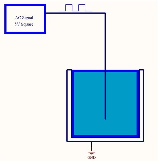
The circuit is as simple as possible: A transimpedance amplifier with 0 A input current. This is to be taken very literally because the feedback circuit (R||C) is an air-connection. The node connected to the in- pin is in free air. The common mode is thus 1.25V below the Vs as recommended with regards to low offset voltage.

We measure the output voltage versus temperature. This is a measure of the combined input offset and input bias current, and of course any leakage currents which could be there as well. We checked that the circuit is stable. The circuit is in a metal enclosure as the in- node is very sensitive to electric field pickup.

Below 30oC the output voltage is generally below 1mV. But gradually raise to from 3mV to 4mV at 70oC.

Datasheet specifies:
Voffset <2mV over extended temperature range.
Voffset drift is maks 2.7uV/oC => or maks 0.10mV at 40oC change.
Ibias is maks +-50pA at 25 oC => 10Mohm*50pA = +-0.5mV
Ibias variation figure 14: indicate that the bias current should stay below 100pA = 1mV output change. (Is that true?)
So in total this never going to add up to 3 to 4mV. Where is the mistake?

Thanks for any hints you can provide.

Here are the relevant(?) datasheet extracts:

LMP8603-Q1

$
0
0

Dear, Sir.

LMP8603 has "OFFSET" pin for bidirectional current sensing.

The output is 1/2 voltage applying the "OFFSET" is referenced to mid-rail voltage.

The datasheet indicates "OFFSET" pin tied to "VS" under such usage.


Is it no problem that "OFFSET" tied to another voltage source closed to "VS" voltage?

It could be utilized as output voltage offset adjustment if possible.

Is this kind of usage acceptable for LMP8603?

Best Regards,

AMC1100 Theory of Operation

$
0
0

Hello,

Customer is considering to use AMC1100 and requests me the AMC1100 Theory of Operation.

ISO122 datasheet has explanation of theory on page 6, but AMC1100 has no explanation.

Could you supply any document that explain the “AMC1100 Theory of Operation” and internal Block Diagram ?

Best Regards.


load cell signal conditioning

$
0
0

Hi,

I am in the process of designing loadcell. .  I am using a Wheatstone bridge circuit to detect the difference in my voltages with the weight differences.  I am using two strain gauges both 350 ohm and two 350 ohm precision resistors.   I am using the opa2277 and xtr106 as my  amplifier and VtoI converter.I have connected my circuit as per xtr106 datasheet application note.

My problem is when i  connecting opa2277 output to xtr106,then it is loaded.i.e opa2277 output is 415mv means,after connected with xtr106 it is reduced to 15mv.kindly suggest me.

Thanks for your help

jayanthi

Water sense with AC Signal - Cutoff Design

$
0
0

We want to build an circuit of water cutoff

Controlling of water pump motor that adding\stop adding water to a container
The water container maid of metal and the signal in the water should be AC Signal (square 5V)
The body of the container connect to GND

I have only one Entrance\inlet to the container so with the AC signal
I should also fit the AC Signal to the water and also sense the present's of the water
(We must use AC signal)

Another issue - I need design sensitivity of water that my probe feel's (sense) 20Kohm\50Kohm\100Kohm
with AC signal that fitting probe sense

I thought of some idea's
like Voltage divider with the water resistance
or current flow measurement - when my fitting probe (AC Signal) close circuit with the water to container body (GND)

Of course We MCU with ADC to measure analog signals

Please suggest more ideas how can I over come that problem
Measure the present's of the water and sensitivity to water resistance

Thanks in advance

Mayer

Inquiry regarding voltage output swing level on TLV274 and TLV2374

$
0
0

Hello, all

Now we have one inquiry regarding voltage output swing level on TLV274 and TLV2374 from our customer.

They would like to know how much voltage output swing level on TLV274 and TLV2374 would be, in case of adopting VDD=8V and GND=0V, and output impedance is 2kohm individually.

We thank you in advance for your information.

Best regards,


AMC1100

$
0
0

Dear Sir

We’d like to use AMC1100 for current measurement in AC line 230V. Please, see figure. Voltage at VD1  is within ±250mV, if there is no over-current load. If there is over-current load (short circuit in the load), then voltage at VD1 may be 7V shortly (20 ms max, until operation of overcurrent protection).

QUESTION: Is there a need to prevent feeding this 7V voltage to AMC1100 input? And to install VD2 at 3-4V breakdown voltage?

 TIA

Sincerely yours

Vladimir Naumenkov

www.agat.by

OPAX170

$
0
0

Is there a plot of current noise density for the OPAX170? What is the input architecture (CMOS or Bipolar)? 

Thanks.

FAO Paul Grohe RE building a Microgram scale

$
0
0

Hi Paul, I saw your amazing YouTube video: http://m.youtube.com/#/watch?v=n90whRO-ypE&desktop_uri=%2Fwatch%3Fv%3Dn90whRO-ypE

...showing you can accurately weigh an Eyelash hair. I am carrying out a study for an international Conference for Eyelash Extension professionals and have been searching everywhere on how to accurately weigh various combinations of individual Eyelash Extentions. Can you advise me on how I could access something like that? Even to hire or something? My partner is a Electrical engineer so he should be able to help but any advice would be grately appreciated.

The forum that I post on for Eyelash professionals were even considering pitching together to buy a suitable scale (to answer our many questions about this for Natural lash safety) but they're extremely expensive from what I've heard.

Any advice you ( or anyone else) has I would be most grateful.

LOG114, for higher input current

$
0
0

hi my customer want to use this part with higher input current.

From 10nA TO 100mA photo diode.

VOLTAGE SHOULD BE BETWEEN 2.5 and 5.5V

Current mirror doesn't work due to the VBE drop.

Could you please help?

kamal


LMV339 input voltage range

$
0
0

Hello,

My customer uses the LMV339, an input signal is applied when the LMV339 supply voltage is zero.

The input current is less than 1mA and the input applied time is less than 20msec.

Is this condition OK?  Is there no damage in the device?

Regards

Naoki Aoyama

OPA2170

$
0
0

I'm observing that the OPA2170 has Input Differential Over-Voltage Protection Diodes. I do not see these mentioned in the datasheet anywhere.

Can someone confirm this?

I need an amp like this one (low noise, low power, wide supply range) that does not have these diodes.

Thanks.

PGA112/113 offset error

$
0
0

Hi there,

http://www.ti.com/lit/ds/symlink/pga113.pdf

On page 3, it says, the input offset voltage can be +/-100uV maximum

I am not sure how to interpret this info.

If we have AVdd=DVdd=3.3V, Vref=Vin=0.9V, what will be maximum offset error on the output? 100uV regardless the gain?

Thanks for your time!

Clamping Amplifier

$
0
0

Does anyone have any ideas for an amplifier circuit that meets the following constraints:

Power: <10mW

Input Range: +/-15V

Gain: 1V/V, output clamped at +/-5V

Bias Current: <1nA.

Amp Noise: <2uVpp 0.1 to 10 Hz, <50nV/rthz at 1k

Basically i'm trying to design a low noise, low power unity gain amplifier that clamps the output at +/-5V. I don't care about anything above +/-5V, but I don't want to amplifier inputs to draw any current when the input is below +/-15V.

Any ideas?

Thanks!

AMC1100 input protection

$
0
0

Dear Mr Jose Duenas Cuellar!

I thought about circuit in the attached Figure 4  (with TVS or Zener diodes)

Voltage at the R2 resistor may be 10-12 V in overcurrent moment. If to use Zener diodes, then if current flows in I2 direction, then at VD2, VD3 will be voltage 3V and at VINP, VINN will be voltage 3V relatively GND1.

If current flows in I1 direction, voltage applied to VD2, VD3 in the forward direction, then voltage at VD2, VD3 will be 0.7V and VINP, VINN will be 0.7V negative relative GND1. But max negative voltage at VINP, VINN must be no more than 0.5V.

Please, answer 

1) Is it essential that this negative value will be 0.7V i.e. more than 0.5V?

2) Can we use R8 in order to decrease input voltage, if max voltage at the R2 is more than 250 mV?

Please,

TIA

Vladimir Naumenkov  www.agat.by

Viewing all 18983 articles
Browse latest View live


<script src="https://jsc.adskeeper.com/r/s/rssing.com.1596347.js" async> </script>