Quantcast
Channel: Amplifiers forum - Recent Threads
Viewing all 18973 articles
Browse latest View live

Bubba oscillator - damped output

$
0
0

Hello,

     I am trying to stimulate the very basic example of bubba oscillator and the output I am getting is getting damped. I know there's something wrong but not able to find out where. Can anyone help me in this?

I am also attaching the snapshot and the schematic file.

(Please visit the site to view this file)


Please help me remove oscillation

$
0
0

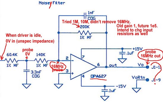
I inherited a special purpose amplifier that included the noise(y) filter below.  Everything in front of the noise(y) filter is working properly.  When things are idle up front, I get about 0V coming into this section.   However, this circuit is oscillating, introducing a 16MHz signal.  

I'm not sure how to get rid of it.  Your assistance would be greatly appreciated.

Do note that I read about the OPA637 being stable above gain of 5.  Also, due to an unrelated problem upstream, I want to increase the gain of this stage from -1 to -1e5 (-100,000).  So I tried putting in a larger feedback resistor, but this didn't change the noise at all.  So, I don't know what's unstable about this circuit.

Note also that I confirmed that the 16MHz is not present on the input, or at the middle of the incoming Tee filter.  I checked this just to make sure the problem wasn't with my scope or ground, or some snafu like that.

Generate 150Khz using bubba oscillator

Non-linearity of LM7301 op-amp with high current load (~4mA)

$
0
0

I recently tried to load the output of a circuit which was being driven by an LM7301 op-amp. The load was around 1K and the output was DC and adjustable from 0v to 4v. The input to the op-amp was a DAC output, 0 to 3v, known to be linear. the LM7301 was set up with positive gain of ~1.3 to give a 4v full scale output. When we measured the output voltage on the LM7301 we discovered it was not linear, there were errors in linearity of up to 3% at some points. With a 10K load or higher it was OK.

Using a gain of 1 by shorting out the feedback resistor improved the linearity a little but did not solve the problem completely. We were using 5V supply voltage, when we increased that to ~7V the problem seemed to get worse.

Can anyone suggest why this is happening and how to prevent it?

The LM7321 is suggested by TI as a higher current replacement, does it not have this problem?

Are there other op-amps with the same pin out (SOT23) as the LM7301 which behave better, the LM7321 is not good for me as it has >1uA input offset current.

ultrasound (piezoelectric sensor) amplifier

$
0
0

I try to use LMH6624 to make a prea-amp for a piezoelectric sensor. I chose it for the wide band and low noise characteristics. I tried to use it in a traditional circuit where imput resistor is 1M or higher. Due to high bias current it blocked the OA. The specs says that one of the application is ultrasound preamp. Can somebody provide a schematic using this OA in such application (piezoelectric sensor)?

Thank you

Strain Guage to 4-20mA Current transmitter with XTR115

$
0
0

I have 3 wire strain gauge sensor. And I want to transmit this signal through 4-20mA current loop using XTR115.

So kindly guide me with this.

Thank you.

INA333 temperature and signal noise

$
0
0

Hello ,

We are using a 5000-10000 pcs of INA333 AIDGKT for our production.

It happens that  2 to 4 pcs every 100 are discharged from test for eccessive analog noise (10-50Khz , 5 to 10% of FS) from INA333 .

We thought about other problems , but now we found that the real problem is the temperature on INA333.

If we locally cool INA333 to 5-10 C or heat INA333 to 35-45 C noise disappears completely , but then returns

with temperature in 20 C range area.

Have you experienced something similar ?

INA333 batch we surely found this issue is 36A P2GD series (seen on back of chip).

Thanks

Maurizio Milani

INA327 GAIN PROBLEM

$
0
0

Hello I am trying to use INA327 to amplify the output of LMP91000.

The problem is that I cannot get in the real circuit, the simulation results.

This is the circuit:

To get the curves I use:

The DC transfer characteristic at the output of LMP91000 is:

And the simulated DC transfer characteristic at the output of INA327 is:

Which is the voltage swing I need to feed to the ADC.

The problem is that when measuring in the real circuit I do not a stable INA327 output voltage, and in the order of mV.

I have soldered R1 resistor directly to pins 1 and 10.

What can be the problem be ?

Thanks you.

Best regards,

Alejandro

(Please visit the site to view this file)


AFE032 RX_PGA1 Input resistance

$
0
0

I feel something weird about the input resistance values mentioned in the datasheet. I expect the input resistance to be inversely proportional to the gain, but the values seem discontinuous. Please confirm if the values are correct, especially for Gain values of 1, 0.5, 0.25, 0.125.

AFE032 FCC Application schematic

$
0
0

I intend to use AFE032 for FCC band PLC Modem system, on a 24V DC line. How similar will the schematic be, having the DC PLC Reference Design for AFE031 as the reference.

Will the line coupling circuits be the same?


Please mention other considerations which has to be accounted for.

How to do Icp circuit using operational amplifier, which provides power and output voltage

$
0
0

How to do Icp circuit using operational amplifier, which provides power and output voltage

LMV721 Current Sense amplifier for Hbridge DRV8833

$
0
0

Hi

I need to measure the current sensing for Hdridge driver, in my design iam using DRV8833, the Hbridge driver have current sensing pin. so iam using current sense amplifier to measure the current.

please find below image of my Hbridge circuit, so iam using LMV721amplifier to measure the current, i would like to know what is the best way to connect hbridge current sensing pins to this amplifier. please elaborate.

Please suggest the amplifier which we selected is good for current measurements. FYI: the output of the current amplifier is connected to the ADC pins of the MCU.

Regards

Anil

Single channel version of OPA2111

$
0
0

What is the single channel version of the

OPA2111 TO99 or

OPA2111 PDIP

http://www.ti.com/product/OPA2111

LMP7721 evaluation board J1 & J2 connectors

$
0
0

Hi Ti,

Recently I purchased a LMP7721 evaluation board for one of the low current measurement application. (I want to measure the current generated by charged aerosol particles condensed on to an electrode. Which is in sub-femto amp range). I have some questions to clarify.

1. I watched Paul Grohe's video on cleaning procedure, however, when measuring input biased current, I am getting positive voltage reading. Why? ( Paul Grohe's video it's negative, I followed exact same steps, except I'm using single supply, 0-5V)

2. In the data sheet pages 13, 14, and 15 on hardware schematics, out put connected to J1. Again I am confused? Isn't it to be J2?

3. Again in Page7, Vout=I/RF. Is this a typo?

I am from mechanical engineering back ground, some of these electronics stuff are really new to me. Your help regarding this will be greatly appreciated.

Thanks

~Ishara

There is no FilterProv3.0 filtering software

$
0
0

There is no FilterProv3.0 filtering software


XTR300EVM pin

$
0
0

Good day friend,
I bought XTR300EVM with oldest version, and I was confused because the evaluation board is different with in the datasheet. Please could someone help me to set the jumper, because there is no jumper on evaluation board.

ina333 common mode vs. gain

$
0
0

I have a very simple ina333 application with a static deltav of 10mv at the inputs, gain of 100, single supply +5,0V.  Vref set to 0V.

The output is 1V as expected with the common mode above 500mv.  Once the common mode drops below 500mv, the gain starts dropping off.   I see this in my board (unfortunately), and also in a Tina simulation.

Datasheet says cm > 100mv should work.

Why do I see gain changes below 500mv?

In the attached simulation, if you change V5 below 500mv you will see the gain gradually drop off.

compensator designing using OPAMP

$
0
0

Dear All,

      I am new in feedback control system designing.

I have come across concept of compensator designing to stabilize system & implimenting poles & zeroes in system for that.

But how to design it & not able to find good & straight forward document on this topic ??

Can you suggest me some links for that which will be helpfull for compensator designing using OPAMP ??

I am using OPA2140.

& any simulators from TI & all for reference.

Looking forward for your support.

Thank you.

TLE2062 Output Impedance

$
0
0

Hi,

The open loop impedance of TLE2062AM is given as 560 ohm.

Why it is very less in Figure 23?

Thanks,

Shihab.

INA116 with multiplexer?

$
0
0

If I want to use a multiplexer to switch between channels using the same INA116, how could this be done?
As I have tried connecting them to multiplexers, but seems channels will have affect on each other, so see what could be done.
Anyone have experience on this?

Viewing all 18973 articles
Browse latest View live


<script src="https://jsc.adskeeper.com/r/s/rssing.com.1596347.js" async> </script>