I am using opa211 in msop-8. sometimes it is very hot. and it has no powerpad (heat dissipation pad) on the bottom.
could you give me some advices?
thank you.
Zhang
I am using opa211 in msop-8. sometimes it is very hot. and it has no powerpad (heat dissipation pad) on the bottom.
could you give me some advices?
thank you.
Zhang
Hello,
I'm interested in building a device that can measure GSR.
While researching it over the web, I found several electronic circuits, however, the one that I saw feels like toy circuits. I was wondering if any of you can recommend on a good proven design as well as TI's components that can help me in building high quality circuit. I did notice TI's INA126 amplifier but I'm not sure if this is the correct direction.
Regards,
Mike
Hi,
My question is regarding matching the source impedance of a non-inverting configured op2134 with the parallel impedance of its feedback resistors. The circuit is such that the input from the instrument will be ac coupled into the + terminal followed by a 1Meg resistor to gnd from the + terminal. The output impdance of the instrument will vary (100 ohms or less up to 100k+) due to it being active or passive. According to page 9 of the OPA2134 data sheet, the Source impedance should ideally match the parallel resistance of the feedback resistors for lowest distortion.
Do you have any recommendations as to what the best value range these feedback resistors should be for this application.
Thank you,
Jim
Greetings,
I've done some reading on this matter, and I came to a problem about interfacing amplifiers with ADC's. I have an amplifier (INA116) that produces a single ended signal on its output pin in respect to the reference voltage that is tied to the ground in this case. The amplifier also has dual/bipolar power supply, so the signal can swing from negative to positive voltage and is therefore bipolar. Let's assume the amplification is maximum possible, so the output voltage can swing between the positive, and negative voltage supply i.e. +/- 10VDC.
Next, I would like to measure this signal with an ADC. Currently I have a ADS1100 in stock. It is a differential ADC, that is supplied on +5VDC, and it cannot accept negative voltages on its Vin+ and Vin- pins. Therefore it requires a unipolar differential signal.
I would like to know what is the best/easiest way to measure this bipolar single-ended signal with a differential ADC like that. Obviously it has to be converted into tolerable levels, and then split into two signals (by an inverter?). I'd like to use the ADC's full measuring range so I do not wish to lose 1 bit of precision, but I don't want to introduce too many components to keep noise to a minimum. Are there other/better solutions i.e. should I get a better single-ended ADC instead? Can measure a half-range, and use the ADS1100 PGA = 2 to turn it into full range?
Kind regards!
Hello Champs,
I have a customer - planning to use XTR115 in our HART compatible devices. XTR115 is not compatible to HART specification because of its current mirror design.
Can i Know if he can use it as output stage in our HART compatible products?
Thanks
Prashanth
I am following this TI application note for PH meter design and I was advised by Sem from TI to use LM7711 chip in place of LM7721 (which was originally in the design note) for price consideration.
my circuit is on pcb , and i have kept the tracks short but I am getting strange behaviour from the circuit. Its putting out random voltages at the output and seem to loop between values from 0.0 to 50.0 .
I measured signals at two points and i have put the pics . PH1 shows the measurement at the junction of R1 and R2.
PH2 shows the signal at Vout.
why am i seeing an AC form instead of a DC
signal ? does using 7711 instead of 7721 requires some
circuit changes ?
Iam using the PH probe from a working PH meter so i know the probe is good.
please help me out with this since this is the only thing holding my project at
the moment.
I am also attaching the Eagle CAD circuit and board layout for this.
thanks
Can OPA130 be powered by a single ended supply (i.e., V- = 0V, V+ = 36 V max), as long as the specified input common mode range is satisfied?
Thanks
Hi,
Sorry to be a pain, but although I am able to derive the gain of a two opamp instrumentation amplifier without the external gain resistor (Rg), I am somewhat confused about deriving the gain with Rg in parallel with the internal resistors. Can anyone point to a reference or an explanation for what happens in such a setup where there appear to be two feedback paths ? I hope this question makes sense.
I would like to confirm the gain error of AMC1200-Q1.
For one IC, the gain error is fixed. Is it correct?
(ex. one IC: +/- 0.3%, another IC: +/- 0.6%, one IC does not chage
the error (ex 0.3% --> 0.6% --> 0.3% in one IC).)
Best regards,
Atsushi Yamauchi
In a programmable current sink I plan to use a power mosfet. This has a significant gate capacity (several nF) which cannot be driven by the opamp directly – at least not in a speedy manner, so I want to put a gate-driver in between.
The circuit looks like ´this in broad terms.
The gate driver drawn is just an illustrative example.
It is easy to find gate drivers, but the vast majority are for digital application – i.e. they typically have hysteresis in the input. This is not god for an analog application like this where precision and speed are key elements.
I can of course build my own gate drive from discrete components similar to the illustration, but I would expect this to be a problem already solved in an integrated manner.
Can you help me determine if TI has an analog gate driver solution?
Thanks for any advice you may have.
I am using an OPA551 running on +/-15V supplies, connected as a unity gain non-inverting amp. With a 1kHz signal, the output is clipping at about +/-14V with 100k load (as expected), but at only +/- 8.3V into a 33 ohm load (250mA peak). When I apply a 10 ohm load, it clips at about +/- 6.5V (I would expect it to current limit with this load).
Is this expected behavior? Does the output stage run out of headroom at 15V?
The Vout datasheet specs are all at +/-30V supply, so I'm not sure of performance at +/-15V, other than the Isc vs. Vs graph in the datasheet seems to indicate it should not be entering current limit with a 33 ohm load until about 12V peak.
Thanks!
I am trying to configure the settings of the LMP91200 EVM to do temperature measurements and use other settings than the default values. I have a microcontroller with an SPI library included in the IDE and I have triple checked my connections to the EVM. But for some reason I cannot successfully rewrite the settings. I think a standard SPI communication should be four steps in this order:
1) set slave select low (CSB in the case of this board) to begin communication
2) send address of desired register via SPI
3) send 16-bit setting into address specified from step 2
4) set slave select high to release board and shift new setting into register.
This is my understanding of a standard SPI write cycle. Is the write cycle for the LMP91200 EVM different? If my procedure is correct, what is the address of the configuration register? It doesn't say anywhere on the datasheet what this address is. I know on the LMP91000 datasheet there is a register map of all the I2C addresses and their respective settings...
Many thanks,
Will
Hello,
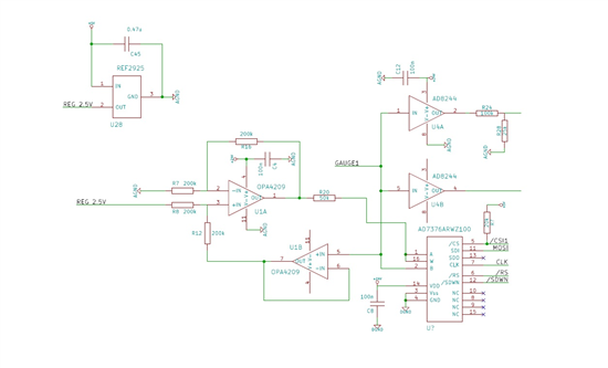
I'm using quad OPA4209 as current sources, as in the schematics below. I have two same channels, using the same voltage reference REF2925. The digital potentiometer is set to 75 kOhms, making the total resistance between PIN1 and PIN5 of 125 kOhms. The potential between these PIns is set by the REF2925, and is equal to 2.5V, allowing 20 µA flowing throw a resistive load (100 kOhms for example) plugged between GAUGE1 and GND. So, the potential of GAUGE1 is: 20µA*100kOhms = 2V.
Despite goods voltages levels, the OPA4209 heat very quickly... I don't find the issue...
I've already try to short the input of potentimeter, but the heat problem still happen...
Thanks for help!
Arnaud
Hello
We are interested in using the INA826, Instrumentation amplifier because it has a good EMIRR rating and a low 0.1Hz to 10Hz pp noise voltage rating. The application we have uses a sensor with an input impedance of around 380ohms at low frequency band of a few Hz.
We have apparently experienced popcorn noise problems in the past with the IN118/INA128 amplifiers.
Can you tell us - does the INA826 suffer from popcorn/burst noise (since it is bipolar and not a chopping device)?
if it is susceptible - are there any screening processes in places to 'catch' affected devices and what
percentage of production is likely to be affected.
Any alternatives?
Many Thanks
Hi team,
What degradation can be expected to the specs of OPA404KU if it is operated at -40 deg C?
Is there a recommended physical drop in replacement for the OPA404KU that can operate at -40 deg C?
Is the OPA4171 a good replacement for these temperature ranges?
Thank you,
Trenton Reed
Hello,
i want to design a summing amplifier to sum up four AC signals (3 Vpp each) of same freq but very low.
Signals are from 4 diff sensors and so the frequency of the signals can vary from 1 Hz to 100 Hz.
Low noise is also critical for the application.
can someone suggest me which opamp IC would be perfect for this application.
Thank you in adavnce,
Hello,
We designing a custom board with PGA280 and ADS1292. We measure about +20 to - 30mV of offset voltage at the output of the PGA280. Would you please help us to resolve the issue ?
What can cause such a very low offset device to produce this much of error ?
I have enclosed the schema of the circuit.
Regards,
Mehmet
Hi
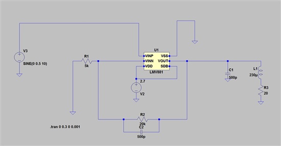
I am using lmv881 in order to generate a 10 Hz 2.5V sin wave - (2.5*abs(sin(2*pi*10*t)))
I connected the the amp according to the picture below (20ohm + 230uH is my load).
from my simulation I have seen that this should be working
when I connect it to my circuit it worked without the load but when connecting the load the Vdd starts to noise and jump in the same freq the sin wave (10 Hz) this influence my whole circuit and this 10 Hz noise reflected on any signal in the circuit .
why is that happening? and how can I fix it?
Hi Team,
Our customer is studying about input sequence.
Because, they are concerned that the normal output(Vo) is not output by an input timing of the input voltage(VI).
After the supply voltage(V+=1.8V) is applied, when can we input the input voltage(VI)?
So, we would like to know about waiting time of the following picture.
Please let me know it if you have a recommended waiting time.

Regards,
Kanemaru
Hi
can you provide me Tj data of LM339APWR and TL431ACDBZR?
I try to calculate by Tj = Theta Ja * Pd + Ta
but for those part, i do not know how to get Pd.
So please let me know how to get Tj data.
thanks.