Dear sirs.
I want to know min value of Ifb(feedback current) of TL4051AQDBZR.
I can't see it in the datasheet and see blank.
Please advise me.
Dear sirs.
I want to know min value of Ifb(feedback current) of TL4051AQDBZR.
I can't see it in the datasheet and see blank.
Please advise me.
Hi,
I am using opa129u to amplify the current. when i connect the output of the op-amp to CRO I am getting a periodic sine wave of 10 volts peak to peak with a frequency of 100 Hz.
I have attached my circuit diagram along with. please suggest a solution to this problem
Hi all,
I have an analog coming from a BNC cable thus single ended. Now I want to digitilize it using 16-18bit ADC. In this case, is there any advantage of using a differential ADC?
I understand the advantages of differential ADC and common mode rejection, but if the analog signal is coming from a single ended input.. the only thing I can reject is the noise between the single-ended to differential buffer and the ADC itself. I am maybe missing something here!
Thanks
Paul
Hi
I'm using OP2277 SO8 parts in a low noise design that we have been producing for around 10 years. I have recently produced a batch that uses 2 x OP2277 parts per channel and have experienced intermittent low frequency 'popcorn' noise which has disappeared when I have substituted devices. Apart from the noise the devices appear to function correctly.
Is this a problem that you have seen before that might be a batch problem? Can you test the parts if I return them?
Thanks
Ian
Hi All,
I have doubt in configuration register. I have checked pH and temperature value by using LMP91200 evaluation board , SPIO-4 evaluation board and sensor afe and found configure the register first and then got the output of pH and temperature. Here I have configure register for pH and temperature separately.
I am making pH meter and using LMP91200 IC. I should required configuration of register one time and get the output pH and temperature value togather.How can I configure the register value ? Please help me.
Hi
I am trying to apply zero crossing detector using lm211.
this is my signal but I cant get this circuit to do what I want.
I connected emiter out, in- and vcc- to gnd. in+ to the signal below. collector out and vcc+ via 20kohm resistor as shown in page 11 of that datasheet but the output is on high all the time.
why isnt it works?
is there a better way to do what I want (the smaller cheep is the better).
thanks in advanced,

G’Day
We are in the process of designing a PCB based on the TI reference design - TIPD126_SCH_revA. The PGA309 will communicate with a 8051 mcu on I2C for access to the eeprom registers. The Vout will be read by an ADS1110, also with I2C.
Parameters are:
Internal Vref: 2.5V
Internal Vexc: 2.075V
Rbridge: 1000ohm
Vout_z: 0.2V
Vout_fs: 1.224V
V/V: 1mV/V
Vsa: 5V
Course Gain: -8.500mV (calculator)
FE PGA Gain: 128 (calculator)
Zero Dac: 1.140V (calculator)
Gain DAC: 642.570m (calculator)
BE PGA Gain: 6 (calculator)
4-20 mA circuit:
R4 + R5 = (Vout_max - Vout_min) / (Iin_max – Iin_min)
= (1.224 – 0.2) / (0.0002 – 0.00004)
= 1.024 / 0.00016
= 6.4Kohm
R4 = 3.16Kohm
R5 = 3.24Kohm
Iin_min = Vout_min / (R4 + R5)
= 0.2 / 6.4Kohm
= 0.00003125mA
Iref = 0.00004 - 0.00003125
= 0.00875mA
R2 = 2.5 / 0.00000875
= 285.714Kohm
~ 287Kohm
C10 = 1 / (2 * pi * R4 * 1.41) * 1000
= 35nF
~ 33nF
fc_act = 1 / (2 * pi * R4 * c10) * 1000
= 1.526KHz
I have some questions regarding the design:
Thanks
Cheers
Dirk
Hello,
The LMP91000 is a nice chip (and even has internal temp sensor which is very handy for EC cells) but it's designed for 3-terminal EC cells.
However, our application requires more precise measurements and we are trying to use the new 4-terminal EC gas sensors. The 4th terminal is an auxiliary electrode which corrects for voltage drift:
http://alphasense.com/alphasense_sensors/B4_sensors.html
for example: http://alphasense.com/pdf/COB4.pdf
Has anybody successfully used the LMP91000 with a 4-terminal cell?
We are currently planning to just connect the 3 standard electrodes to the LMP91000 and then just run the 4th auxilliary electrode directly into the ADC on our microcontroller, so we can do a correction in firmware; but if there is a better way to do it, we would be interested to hear from other research folks.
thanks,
-RF
TagSense, Inc.
Hi all,
I would like to ask for review of schematic for AC volatage detection.
The circuit is as below.
- input voltage level: 0.6*(18.5, 23.52, 30.49, 38.89, 45.86V) <- RF50_VDET
- input voltage is changed as above values depending on system
- the circuit is to detect over voltage
Could you review the circuit?
If there is wrong values and location of component, please recommend the proper value and location.
Thank you.

Best regards,
Sammy Jeon.
We are designing constant current source , circuit as shown in TI application note AN-1559 Practical RTD interface solution. (Refer Figure 2 page 4) . link : http://www.ti.com/lit/an/snoa481b/snoa481b.pdf
We are designing circuit using TL431 as reference ( 2.5V refernce ) , LM324 OPAMP , R8: 2.49K .
R6 = R10 = R9 = R7 = 22K . Single supply for OPAMP 5V , 100 ohm resistor is connected as Load .
Expected : Current through R8 is 1ma ,
Observation : Refernce Voltage generated : 2.496 V , Voltage Across R8 : 2.86V : Current through R8 1.15 ma ,
Question :
1 ) Why Voltage across R8 is not 2.5V ? Is any changes required in value of R6,R10,R9,R7 ?
2) On what basis the value of R6,R10,R9,R7 are desided ?
3) By only changing R8 what will be range of Constant current that we can design ?
Can anyone confirm the drop in replacement for the 4136 as being the TL075 or the TL075CN? Also, what does "CN" mean?
Thanks,
Tony
Hey,
I would like to use an INA333 to do measure. But some time I switch off INA supply (to reduce energy consumming) and the input signal could have a positive or negative value (arround +/-700mV).
If I do that, can I deteriorate my INA333 ?
NB : input signal and INA supply haven't the same reference.
Thanks for your help
Hi all,
When I was looking at the user's guide of DRV10866, I cound find that the schematic circuit of TLC555(page 8) is different with the circuit of datasheet.
I didn't understand why output pin connects to variable resistor and how to operate the circuit.
would you explain what is the different between two circuits?
Thank you.


Best regards,
Sammy Jeon.
Hi
OPA2277
If RC filter is connected between input terminals, PSRR will get worse.
Please let me know the cause by which PSRR gets worse.
Configuration of RC filter(xyz.png)
Best regards
-----------------------------------------------------------------------
The following texts should be disregarded. It is the error of Editer.
(TPA2006D1)
Dears,
Is there anyone can support AMC1200 PSpice model for OrCAD v16.5?
Only I can find on TI website is the model for TI-TINA.
Or any way to convert TI-TINA to OrCAD model?
Thanks.
Hello,
I am a chemistry student, and I'm currently trying to build a custom pH meter. I've decided to use the INA116 amp because it provides its own guards, and has an increddibly low input bias current. This is perfect for pH electrodes that have internal resistance of several hundred megaohms. However after reading the datasheet I have a few questions about this IC.
A) First of all I'd like to know a few details about the input bias current path. The datasheet suggests (page 8, figure 3) that some resistors be connected between each amplifier input pin, and the ground. According to that schematics I see two 100 MOhm resistors connected to each input, and the ground. Is this correct - are these really needed in my case? The sensor I will be using is a pH electrode, and they have internal resistances up to 1000 MOhm. So basically what we just did here is connected a 200 MOhm resistor in parallel to the INA116 inputs.
This means we just added a low-resistance bypass path for the already-weak current that is originationg from the electrode. We are basically measuring the voltage drop on the 200 MOhm resistor, not the pH electrode. The resistance/impedance of the INA is so high that it can be neglected. The pH electrode gives a voltage of 413.7 mV at best, and let's assume the internal resistance is 1000 MOhm. The total resistance of the current path is therefore 1000 + 200 = 1200 MOhm. According to ohm's law (I=U/R), the current at this voltage will be 3.4475E-10 A. That's about 0.3 nA or 344.75 pA. The voltage drop will therefore be U=I*R, and the resistor causes the voltage drop of 68.95 mV, where the electrode has a voltage drop of 344.75 mV due to its internal resistance.
We're therefore measuring 69 mV instead of 413 mV - that's about 83% rel. error we are causing by adding these two resistors here!
What os the proper solution to this?
B) The datasheet also states that guards should fully encircle both input pins on both sides of the PCB. In this case how are the former resistors (assuming we're measuring a lower-impedance source, so that the previous question doesn't apply) supposed to be connected to the input pins? Can they be connected over the guard?
C) What is the maximum output current that INA116 is able to provide? According to the datasheet on pg 2, this would be +5 / -12 mA. Is this correct? If so, what is the proper way to level-shift the voltage to adapt it for a 5V ADC like AD7791? A resistor voltage divider can cause a large error in the ADC measurement. Too low resistor values cause a large voltage drop. Too high, and the ADC doesn't get enough current. What's the proper way to voltage-shift, if the INA is being powered by a single-end power supply of 12V, and has a virtual ground of 6.0V? The ADC is on 5VDC (12V => LM7805 => 5V).
D) Can you offer any other tips&tricks, hints, comments or suggestions about pH meter design?
Thanks a lot.
Best regards!
The data sheet for the INA333 mentions that it contains RFI filtered inputs . Is there such a thing as a EMIRR rating
for this amplifier (as quoted for some precision amplifiers) ?
Also are there any plans to add the EMIRR rating as searchable parameter for selecting amplifiers?
This would be very helpful.
Thanks
Sir,
I am creating a Highly Accurate Constant Current Source for LED using REF5025I as a voltage reference that will provide me a constant voltage of 2.5V and connecting its ouput to the input of XTR111 to convert it into a constant current of 25mA (Rset= 1K)
My problem is that my XTR111 is getting very hot. A capacitor of 470 nF and two resistances(5.6K,8.2K) are connected across REGF and REGS pins. A mosfet BSP170P is also connected in the external current limiting circuit as shown in the datasheet application note.
Instead of these precautions,the IC is getting really very hot.What can be the reason for this and how can I rectify it so as to let my LED glow?
I have attached a bmp image of my schematic.
Thank you in advance
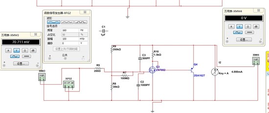 Circuit simulation and why not, high input impedance input charge signal output, why not ah, DC bias is wrong
The LMP91051 is specified as a thermopile AFE. Can it also be used with pyroelectric detectors?