Quantcast
Channel: Amplifiers forum - Recent Threads
Viewing all 18799 articles
Browse latest View live

Photodiode amplifier Evaluation board

$
0
0

Hello, I am looking for an Eval platform that a photodiode can be attached to for measuring the light output of an LED.

Red 530nm, green 630nm, are the LED's that will be used.

Does TI have an Eval platform for photodiodes, or one that can be adapted to such?
Thank you.


Inquiry regarding voltage output swing on OPA192

$
0
0

Hello, all

Now we have one inquiry regarding voltage output swing (Vo) on OPA192 from our customer.

Please refer to the item below, and feedback us with your comment.

When referring page 3 of this datasheet, the positive rail of Vo is defined in case RLOAD=10kohm and RLOAD=2kohm individually.

However, they would like to know the case when RLOAD is more than 100kohm.

Please let us clarify how Vo value would be on this case.

We thank you in advance for your information.

Best regards,

LOG114 single supply operation

$
0
0

Hello. I want to operate LOG114 from single supply. The application circuit in Figure 10 of the datasheet shows the cathodes of the diodes to be connected to GND, where Vcom is connected to Vref. Is this a correct connection? Should the cathodes not to be connected to Vref at least, the potential of the anode side?

A second question is, is there a need to bypass the Vref pin with a capacitor? This is not mentioned in the datasheet. 

Thanks in advance.

OPA 365 + FTZ869 as laser driver

$
0
0

I want to use the application of opa 365 to make a driver for laser diode .  and when i saw a nice laser diode driver design, coming from Texas Instruments's  SBEA001 (the "Laser Diode Driver 1") by Neil P. Albaugh ,  i thought it is a good design for laser driver .  but i can not find the exact datasheet for FTZ869 . i think it is wrong in the design and that transistor should be FZT869 . Am i right ?

AFE4490 EVM

$
0
0

Dear all,

I bought a AFE4490 EVM, and try to get SPO2 data by using a AFE44x0SPO2EVM GUI.

I followed the step of quick start guide (http://www.ti.com/lit/ug/slau480c/slau480c.pdf).

Unfortunately, when I clicked Capture button, the message show that "Reading stopped without returning the expected number of samples. Please check the device and the inputs. Other error message show that " Insufficient number of samples for FFT calculation"

Any one have experience like that. Please help me to solve this problem. Thanks

Sort

AFE031 SPI Trouble

$
0
0

  I am trying to interface the AFE031 via SPI to control the DAC. The output is changing as I write to SPI but not as I expect. I suspect that the SPI mode is incorrect, is there a way to tell the AFE031 which mode to expect? I have read the data from a logic analyzer and am quite certain that my SPI signal is sending the proper data. Any other info regarding the AFE031 would be very much appreciated as  I find the datasheet and Analog Front End Design Note to be very brief.


 I have attached my code and would appreciate if you could take a look at it. It is very simple

http://pastebin.com/pjkMQaN4

dudas con AFE031

$
0
0

estimated

could help me with the following questions that I have about AFE031.

setting the AFE031 in two-wire mode and connecting directly E_Rx_OUT E_Tx_IN and Tx / Rx USART of MCU. Is it possible to establish an asynchronous serial communication (baud rate 19200)?

the output levels of the PGA of E_Rx_Out can be configured as CMOS outputs?

take as a reference page 33 and 34 of the datasheet

thank you very much for your support!

best regards

Cesar Zicker...

Driving FET gate using TLV3501

$
0
0

Hi all, 

To drive FET gate, I am going to use two pulses.

one is made of inverting hysteresis comparator for high side and the other is made of non inverting hystresis comparator for low side.

The dead time is needed to avoid that high side and low side turn on simultaneosly.

I would like to know whether this concept is right or not.

Please give me some advise.

Thank you. 


LMP8603 Bidirectional

$
0
0

Dear, Sir.

LMP8603 has "OFFSET" pin for bidirectional current sensing.

The output is 1/2 voltage applying the "OFFSET" is referenced to mid-rail voltage.

The datasheet indicates "OFFSET" pin tied to "VS" under such usage.


Is it no problem that "OFFSET" tied to another voltage source closed to "VS" voltage?

It could be utilized as output voltage offset adjustment if possible.

Is this kind of usage acceptable for LMP8603?


Best Regards,

[LM10] Spice Model

$
0
0

Hi Team!

I was wondering if there was a spice model for the LM10 that can also account for the effects of temperature. I looked online, but could not find any spice model for the LM10.

Thanks,

Ben

OPA2171 Reflow recommendations

$
0
0

Greetings E2E,

Please advise on any recommended reflow Oven Profile for the OPA2171.

regards

Madhuri

INAEVM Mechanical Drawing

INA125P interface with ADC of Microcontroller

$
0
0

Dear SIr / Madam,

I am trying to interface a loadcell with controller's PLC which can read 0 - 10V or 4- 20mA of analog signal.

I tried to interface loadcell with PLC but got failed. After some searching on web i became to know that INA125P helps to interface loadcel with other devices. So i order sample of INA125P to try.Unfortunately the same result repeats here also.

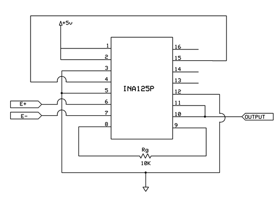
I used the connection same described in starting of datasheet of INA125P. Used Rg =10k and sleep tied up with VCC.

Used power of 5v which is regulated from 7805.

Loadcell details:

 Red - V+ : 5VDC

Black - Gnd : Gnd

Green - Signal +

White - Signal -

Operating Volt : 5vdc

Maximum Load :3kg.

when i checked the signal output using multimeter its showing +2.5v for both signal of loadcell without any load on loadcell and not connected to INA125P. but while connected to INA 125P its showing some mv on meter and it varies each poweron time. but not varying output while applying load on load cell.

why it is like this?

Does i did any mistakes in wiring ?

I am trying to get voltage varying output to interface with PLC analog module. Please help to  overcome this issue.

Enclose herewith the schematic diagram of INA125P. Find the diagram for more details.

Regards,

Nikhil V V

Input Bias Current vs Input Impedance

$
0
0

Hello,

   I was wondering if anyone might be able to explain the relationship between the "input bias current" spec and the "input impedance" spec.  Is there a way to calculate the total input bias current using the specs from the datasheet, or is it a very nonlinear/non constant?

-Mike

FAO Paul Grohe RE building a Microgram scale

$
0
0

Hi Paul, I saw your amazing YouTube video: http://m.youtube.com/#/watch?v=n90whRO-ypE&desktop_uri=%2Fwatch%3Fv%3Dn90whRO-ypE

...showing you can accurately weigh an Eyelash hair. I am carrying out a study for an international Conference for Eyelash Extension professionals and have been searching everywhere on how to accurately weigh various combinations of individual Eyelash Extentions. Can you advise me on how I could access something like that? Even to hire or something? My partner is a Electrical engineer so he should be able to help but any advice would be grately appreciated.

The forum that I post on for Eyelash professionals were even considering pitching together to buy a suitable scale (to answer our many questions about this for Natural lash safety) but they're extremely expensive from what I've heard.

Any advice you ( or anyone else) has I would be most grateful.


Problem with LMP7721 for Charge Amplifier

$
0
0

Hi,

I use the LMP7721 to build a charge amplifier. Two 560K resistors are used to divide the 3V single supply. So I get the 1.5V as the commen mode voltage and have it connected to pin 'V+'. Feedback Rf of 1G ohm and Cf of 10 pF are connected in parallel between pin 'V-' and pin 'Vout'. Pin 2 and Pin 7 are used to build the Guard. Guard trace is connected to pin 'V+'. The charge amplifier design refers to Figure 6 of OPA129 Datasheet.

The problem I encountered was the potential of pin 'V-' is 0.9V, not equivalent to that of pin 'V+' 1.5V. This may cause LMP7721 saturated, and thus we can't get the right signal output.

Happy to hear your advice.

Thanks,

Eric

LMP91000 and SPIO-4 temperature measurement

$
0
0

Hello,

I have recently purchased the LMP91000EVM with the SPIO-4 board. I have installed the GUI and I have learned how to change the different registers. I currently do not have a sensor, but I would like to start using this setup to measure temperature. I would like to be better familiar with everything before connecting our sensor.

Could you help me measure the temperature in the LMP91000 GUI? I am not sure of the settings I need.

Thanks for your help.

Best regards,

Theresa

LMP2012 minimum input voltage

$
0
0

The LMP2012 datasheet states that the LMP2012 minimum output is 95mV (worst case).

what is the minimum input voltage?

If I use a non inverting amplifier configuration with a gain of 50V/V, can I apply a 2mV input? in that case the output will be 100mV which is inside the output range.

regards,

Itai

LM148J883 versus LM148J883QS

$
0
0

A supplier has proposed the "QS" version as an alternate, and cannot find this designation in data sheet # SLOS058C.  Could you please define what the "QS" is and if parts are fully interchangeable.

Thank you,

Gary Michaels

Configuring LMP91200 EVM

$
0
0

I am trying to configure the settings of the LMP91200 EVM to do temperature measurements and use other settings than the default values. I have a microcontroller with an SPI library included in the IDE and I have triple checked my connections to the EVM. But for some reason I cannot successfully rewrite the settings. I think a standard SPI communication should be four steps in this order:

1) set slave select low (CSB in the case of this board) to begin communication

2) send address of desired register via SPI

3) send 16-bit setting into address specified from step 2

4) set slave select high to release board and shift new setting into register.

This is my understanding of a standard SPI write cycle. Is the write cycle for the LMP91200 EVM different? If my procedure is correct, what is the address of the configuration register? It doesn't say anywhere on the datasheet what this address is. I know on the LMP91000 datasheet there is a register map of all the I2C addresses and their respective settings...

Many thanks,

Will

Viewing all 18799 articles
Browse latest View live


<script src="https://jsc.adskeeper.com/r/s/rssing.com.1596347.js" async> </script>