↧
LMP2012: Output impedance vs frequency curve
↧
LMP7708: Oscillation seen on the band pass filter
Part Number:LMP7708
 Hello Team,
We are working on a band pass filter for an accelerometer. What we see on the output is that for steady state output there is a ~4.8MHz oscillation. We checked the supply and it is a steady state 3.3V supply to the filter and sensor. We removed the DC-blocking caps C7, C10 and C13 and checked the output of the sensor and it shows a clean DC output. However when we connect the scope probe to the any of the cap's we see the oscillations.
The spice-sim we ran on the circuit did not show any such issue.
Attached is the snapshot of the Schematic.
↧
↧
TLV8544: PIR Motion Detection Refence Design Application Problem
Part Number:TLV8544
Hi,
I tried the circuit depicted on below image with TLV8544;

I can capture the motion very well but there are some issues. In the idle state (no motion) there is a 0-2.3V 50Hz square-like wave noise in the whole circuit. I tried different PIR sensors (Murata IRS-B210ST01, Xlitas LHI 968 and non-branded Chinese sensors) but the result is same. I used RC low pass filter with 1.5 MO and 100nF the eliminate noise. Low pass filter is located after Pin 7. I worked but circuit is not stable. I still have no idea why there is noise.

In this image you can see the 50Hz noise after motion detection on pin 7.

Closer look to noise signal on pin 7.
On the other hand, I can not be sure, is this circuit stable (with low pass filter) . After motion detection, I still capture logical one from outputs for some reason and there is no pattern. It stabilizes after sometimes but there is no certain time for stabilization. When I connect any of pins to oscilloscope circuit works like a charm (oscilloscope and circuit grounds are seperate) so I can not see where is the problem. How can I develop a PIR circuit that I can totally trust?
↧
LF198QML: Had it Thermal PAD in LF198QML?
↧
OPA4192: Can you tell me Op-Amp OPA4192IPW supply current
Part Number:OPA4192
HI,
Can you tell me below op amp supply current or how much current take from supply??
1) OPA4192IPW
2) OPA320AIDBVT
3) INA188ID
4) OPA2192IDGKT
↧
↧
OPA4197: Selecting Proper ADC Buffer Amplifier
Part Number:OPA4197
How do I select which op amp is the best ADC buffer for my application? I filtered based on input bias current, noise, etc. but it doesn't seem that every op amp summary page includes "data-acquisition systems" or something related.
I am building a signal conditioning card that I would like to use for general purpose data-acquisition systems. Ideally this op amp will work with any DC or AC input up until about 100 KHz. Other than that I need it to go up to +/- 10V rails, single ended output. There seem to be thousands of op amps to select from, how do I chose which one is best for my application??
↧
WEBENCH® Tools/LMP91000: webench designer
Part Number:LMP91000
Tool/software: WEBENCH® Design Tools
Hello every one
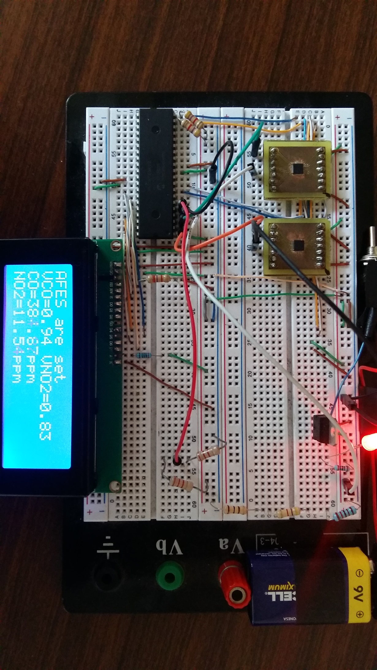
i am working in the development of an air quality monitoring system of two pollutants which are Carbon Monoxide and Nitric Dioxide. I am using the electrochemical sensors 4-CO-500 and 4-NO2-20 whose outputs are in microamperes. So i am also using the lmp91000 to convert this output signals from the sensors in voltage. I used the tool webench designer to set the values of the registers of these IC according to the sensors i am using. I am using a microcontroller to set the AFES through i2c. i check if the registers of the AFES were correctly set printing a text in a display lcd that is going to appear only if all the registers of both afes have the values i put in them. The problem is that when in make the circuit works i measure the voltage output of the afes and i get a voltage without the sensors connected to them and this ones doesn't coincide with the voltage measurement it supposed to be according to the gain set. in the picture is the circuit of how i am using the afes

↧
LOG114: Can I use one of the available OP Amps on the LOG114 as a buffer amp for Vref on the ADC?
Part Number:LOG114
Hello,
I'd like to use the daisy chain feature of the ADS8866, but I understand that using the same reference supply for an external ADC can be problematic if connected directly. Can I use one of the two available OP Amps on the LOG114 as a buffer amp for the ADC? So, the configuration is one LOG114 tied to one ADS8866 with Vref buffered thru LOG114 to provide Vref for ADS8866. I need to do this with three acquisition channels - one per photodetector.
Thank you,
Patrick
↧
log114: Using precision current source from CC2640r2 with LOG114
Part Number:log114
Hello,
I'd like to use the precision current source on the CC2640r2 as the reference current input to the LOG114 (I1 pin 4). This allows me to adjust the current source in firmware from 1 uA to 10 mA. This give me some "scalability" for my photodiode input. Do I need to condition this signal in anyway? Or can I just connect the precision current source from the CC2640r2 directly to pin 4 on LOG114 - no resistors, capacitors, buffer amps, etc.?
Thanks,
Patrick
↧
↧
LMP91200: guard ring, vcm/adc and vref questions
Part Number:LMP91200
I have lots of questions.
I need to measure between 5 and 8 pH for a nutrient controller. While .01 accuracy is nice .1 accuracy will be ok for my application.
First the guard ring appears tp have a pad connection to the triax connector. I have 50 coax type connectors, and all the pH probes I have(many different ones) all seem to have only two connections(center and shield). Do I need a different connector?
Is it okay to have the guard ring only incircle the INP line without any other connection other than the two guard pins?
I'd like to have just a single sided board. App notes recommend a guard ring on both sides. Is it okay to have only one sided ring?
The reference design show both the vout and vcm going to the adc port. I assume I am supposed to subtract the VCM value from the VOUT to get my pH reading. Can I assume VCM is halfway between ground and the VREF voltage and only use one ADC pin for VOUT and subtract 1/2 VREF to get a reading?
Also, once I have the ADC reading is it linear? Can I calibrate to 4, 7 and 10 pH and expect all reading to fail on a linear function? ie. 4ph is 200 ADC value and 10pH is 800 ADC value, then 500 reading equals 5pH? Or is there a formula I need to apply?
Can Vref be the same as VDD? In my cas inputs only?e 3.3V. Or do I need to voltage divide 3.3V to get a lower reference voltage?
I have seen circuit diagram with CAL and RDT inputs.My datasheet says these pins are NC. Is it the lmp91200MTX version that has the RDT?
Since I have a temperature probe for the EC circuit, I could switch it to the RDT line when taking pH measurements if your chip does the temperature compensation internally.
Otherwise what is the formula to compensate for temperature for the pH reading. The temperature range will be between 15 and. 25C.
If I place the chip under a wifi chip and antenna (2.4 gHz on the board will I run into leakage problems?
There ia a reference to both analog ground and digital ground in the datasheet. What's the difference? They all seem to be analog grounds on the pinout table.
Can all GND pins be tied to the ground on my micro-controller?
↧
Photodiode and Trans impedance amplifier
Greetings ,
I am wanting to use a High intensity IR LED and a photodiode to span a distance of 20 meters as a pair for a through beam detector. There are devices like the VISHAY TSOP40xx devices that can do a similar job , but carry the overhead of modulation for remote control. We want a purely analog signal ( High or Low) and do not want the added overhead of adding digital demodulation in the carrier and really dont want a carrier at all. Our issue is obtaining distance with a pair of transmitters and receivers. We wish to use a TEMD1000 from Vishay as the photodiode and a VSMY2940RGX01. If there are other parts from the TI line-up that may be used I will consider this, but I feel I will need an amplifier for at least the TIA. I have been looking over the the Photodiode Webench and trying to determine the requirement of the photodiode. At a distance of 20 meters what will the current flow be in the photodiode with the above mentioned LED. I know that I will need to use the Inverse square law to determine illumancance on the photodiode, but I am having trouble figuring this out. If I had this I could configure the TIA properly.
Thank You
↧
LMP91000EVM: Windows 10 unsigned driver workaround broken for SPIO-4 following recent Windows update
Part Number:LMP91000EVM
I have been using the SPIO-4 board with LMP91000EVM and the associated LMP91000 software on several 32-bit and 64-bit Windows 10 machines for the past year. I am aware of the issues with the LMP91000EVM software in Windows 7, 8 and 10, but the "enable unsigned drivers" workaround posted elsewhere on this forum has been consistently successful.
Unfortunately, it appears that a recent Windows update has broken this workaround. I strongly suspect that the issue is with KB4054022 from Dec. 2018, which is unfortunately not an uninstallable update. Specific details are provided below.
Have any other users experienced recent issues with the workaround no longer working? If someone with a fully updated computer is still able to use SPIO-4, that's helpful to know as it might indicate an issue specific to my computer.
And/or, is there any update from TI on an intent to finally get these drivers signed? In 2013 a TI admin mentioned such an effort, but it seems no public progress has been made in the past 4 years ......
*******************************************
Additional details:
The specific issue is that the updated computer no longer recognizes SPIO-4 in Device Manager. Previously when installing drivers, it was possible to select the board as "SPIO-4" under an "Unknown Device" tab and point it to the appropriate driver folder. Now it only shows under hidden devices as "Unknown Device" under an "Unknown Device" tab, and fails to install drivers. Somewhat contrarily, the Windows hardware troubleshooter does specifically recognize that "SPIO-4 doesn't have drivers installed" but running the troubleshooter yields no results and never asks for a driver location. The board LEDs do light up when the board is connected, and the computer does sound the "USB device connected/disconnected" chime.
This leads me to believe that the issue may not be because of the unsigned drivers. Other Windows users have experienced issues with older USB-connected devices following the aforementioned Windows update.
I am aware that I can do a repair upgrade to eliminate the problematic update, but it would be great for there to be a more long-term, secure fix.
↧
INA826EVM: Rg component size
Part Number:INA826EVM
Hello,
I'm interested in buying the eval board for the INA826 as well as a SMD resistor and cap kit to go with it, but I'm having trouble finding the component size for Rg. From the user guide, it says all the other components are 1206 but it seems that Rg's footprint is a bit smaller.
Thanks!
↧
↧
LM2907-N: Creating A Simple Frequency to Voltage Converter Circuit
Part Number:LM2907-N
I'm having trouble developing a circuit that will simply turn an RPM signal into a 0-5 V signal.
The supplied voltage is 12 V and the max input frequency is 50,000 RPM. The output voltage needs to be between 0 and 5V.
I've already tried to use the Minimum Component Tachometer Diagram on the first page of the data sheet - only changing the R's and C's to meet my specs from above - with no luck.
Thanks in advance,
Gage(Please visit the site to view this file)
↧
TINA/Spice/LMP7701: Voltage control current source overshoot
Part Number:LMP7701
Tool/software:TINA-TI or Spice Models
I am making a voltage control current source with LMP7701 opamp and MJH6284 darlington pair transistor. I want to drive a current of 10 A peak to peak @ 100 KHz and 1 A offset. I have overshoot on my current pulse, I checked the phase margin by braking loop ~89 deg noted. I don't understand why I have overshoot even with this good phase margin. I have attached circuit I used for checking the stability and with actual circuit for reference. (Please visit the site to view this file)(Please visit the site to view this file)(Please visit the site to view this file)(Please visit the site to view this file)(Please visit the site to view this file)
↧
Driver Amp for a Log amp
Hello,
I am working on a ‘video circuit’ that takes the output of a Log Amp, adjusts Gain and offset, and drives the signal differential over twisted pair wires. The output differential driver must drive 50 ohms. Assuming the twisted pair characteristic impedance is 100 ohms, I will place a 100 ohm resistor across driver output. I must drive the differential pair +/- 1V. Accounting for a back termination, the driver should be able to drive +/- 2V.
The Log Amp output will be from DC to perhaps hundreds of Kilohertz. Differential video output rise time must be < 30ns. Fall time < 100ns. Recovery time < 250ns.
Do we have a driver amplifier that can be used for this application?
Regards,
David
↧
AMC1301: Does there have a mathematical formula about AMC1301's out votage and IN votage
Part Number:AMC1301
Dears
there only one form describe the relationship of output voltage input voltage. So does there have one mathematical formula about the relationship about the output voltage input voltage?
↧
↧
AMC1100: AMC1100
Part Number:AMC1100
Hi,
In the document TIDA-00555.
Pg No-5, kindly help me understand why D19 is connected to -5V and what will happen if connected to 0V. it will help reduce power supply complications.
Similarly what is the Maximum voltage tolerance of PIN 2 and PIN 3.
I have made the following circuit
Application- Isolated PMSM motor phase voltage measurement (F28069M)
The motor is subjected to 72V nominal.
The voltage filter pole frequency is about 200 Hz. (Kindly recheck this) [ BOOSTXL-DRV8301 Hardware User's Guide (SLVU974–October 2013) page 6 ]
I am worried about the transients (positive as well as negative) wont damage the AMC1100
The motor inductance is around 33uH axial flux pmsm.
Previously i had a worst experience with ACPLC87 finally i gave up with that part and changed my design i just need to be super confident before making the pcb.
My original post (cant edit it): e2e.ti.com/.../630156

↧
AMC1311: Vos Initial
Part Number:AMC1311
Hi,
The datasheet calls out the offset voltage as initial at 25C. This seems to imply thats there's known drift with time. Is this something we have data on?
Regards,
Jake
↧
INA333: capacitive load capability - dealing with capacitances around 1nF
Part Number:INA333
INA333 has relatively CL capacitance - datasheet states CL=500pF.
I've found that using 1n - even with serial resistor of 1k doesn't always lead to stable output. Some parts show oscillations and some not - it's hard to tell.
I've tested several serial resistor values but when some parts were stable with this 1n/1k setup - other were oscillating even with 1n/4k7.
I'd rather not to use such high resistances in my application so the question arises - what distribution of stability I should expect.
The output is at 1,2V at it's max (that's the reference value for AD7706 converter in my application).
For the parts that tend to oscillate at 1n/1k setup, I've tested limiting the CL and I've found that I'd had to go even below 300pF.
That is a bit too much reduction for me (looking at the AD converter requirements).
So my question is - what solution I could use to be sure that my circuit will not oscillate at some combination of input signal/temperature ?

I understand that my 1nF is twice as CL max of 500pF however 1k separation value is quite large resistance I think.
In the INA333 datasheet there is an application with CL exceeding 1nF - together with 10k serial resistor but as I said I'd rather not use such large values (again - ADC specification).

↧


