Quantcast
Channel: Amplifiers forum - Recent Threads
Viewing all 19430 articles
Browse latest View live

XTR115 followed by a step-down converter

$
0
0

Hi,

I like to use the XTR115 (or 116/117)  followed by a step-down converter (for example TPS54062) to build a 4-20mA 2-wire HART Transmitter.

The following converter should be used to generate a 3,3V Voltage with current higher than 4 mA.


The step-down converter is connected to the XTR-Pins 7 (7,5 – 36V) and Pin 3(IRet).

The TPS54062 datasheet says, it requires a input decoupling capacitor of at least 1µF.

The XTR115 don’t like larger capacitors between Pins 7  (V+) and Pin 4(IO). The capacitor at the input pins should be 10nF or 1nF with HART.

How do I handle the problem with the input capacitors? Is there an application note available on how to connect the XTR with a step-down converter?

Is there any other XTR that works with a converter and HART?

Thanks

Martin


OPA228 input back-to-back diodes activated when op amp saturates

$
0
0

Hello,

I`m using the OPA228 in a non-inverting amplifier configuration (gain=7). In my application, the amplifier output will saturate sometimes and this should not be a problem. But it is.

When the op amp saturates (output tries to go further than supply), the op amp is not able to keep the voltage between the positive and negative input equal to 0V, so, this difference goes up and the back-to-back diodes in the OPA228 inputs are activated. This is the problem. This decreases my amplifier input impedance and it`s not acceptable. 

Putting a resistor in series with the positive input is not a solution, because in high frequencies (I will measure signals until 1MHz) the current drained by the input capacitance of the op amp causes a voltage drop in the resistor. The error would be too large.

Is there some equivalent of the OPA228 which doesn`t have these back-to-back diodes in the inputs (a precision op amp that accepts having voltage differences between positive and negative input)? I have searched for the OPA827, it seems that this part doesn`t have this protection, am I right? But it`s more expensive..

 Best regards,

Alexandre Bueno

Low frequency LP filter based on OPA1612

$
0
0

Good morning.

I'm trying to design a low-pass filter. It's characteristics are shown below. The frequency axis is in Hz.

The filter consists of four sections realized by the schematic shown below. The amplifiers are OPA1612 - SO8.

I determined that output noise for above configuration for the 1 Hz input signal (in=12pA/sqrt(Hz)) will be about 0,7 uV/sqrt(Hz) and for the 0,1 Hz input signal (in=40pA/sqrt(Hz)) will be about 0,12 uV/sqrt(Hz)(calculation from technical documentation of OPA1611). Is that correct?

 What is the peak-to-peak value of that noise?

Another important question is connected with the input impedance. Is that correct that I assume the input impedance of 20 kOhm is multiplied by open-loop-gain in that frequency range?

Another question is about THD (with and without noise). Is there any loss of the linearity in that configuration from optimal value that could be achieved by this opamp? Resistors and capacitors are assumed to be linear.

What else should I consider in designing that low distortion and noise filter?

At the end I wish to ask for some guidelines how to design a good PCB, for example where to place decoupling capacitors of what values.


Thanks

OPA627 PSPICE MODEL QUESTIONS

$
0
0

Hello

I have few questions on the PSPICE model for OPA627

Q1) As per the specification document this part has 7 pins: pin 1- Trim, pin 2- NegIn, pin 3- PosIn, pin 4- Neg Supply, pin 5-Trim, pin 6-Output, pin 7 - Pos Supply

In the PSPICE mpdel I see .SUBCKT OPA627 1 2 3 4 5.

In PSPICE what do these pins correspond to?

Q2) When I unzipped the model file from TI library I also see OPA627E. Upon opening it says E stands for enhancements. Please confirm that it is just the modeling enhancement and not a enhanced part?


Thank you


OP07 vs. TLE2021A or OPA277 for EMI

$
0
0

Team,

My customer has used the OP07 and LT1097 in an application.  He is worried about EMI around the 1-2GHz region.   He would like to compare from a reference point he knows.   We have recommended OPA188 and LMP2021 as other candidates to look at. 

"I found the OP07 was once used in this design before the LT1097.  Going back through the TI website, it looked like the OPA277 and TLE2021A are two matches that I think would both function in my application.  

I reviewed the EMI datasheet and it showed about 19db EMIRR for the TLE2021A and 90DB+ for the OP277 at 1.8GHz, so I ordered some OP277's to try.  It would be fascinating to know how the OP07 and LT1097 rate on that scale."  
 
There doesn't look to be much info in the OP07 datasheet so I was hopeful one of the old timers on the forum may know.  

Thanks,

Aaron

INA333 ECG application

$
0
0

Hello,

We are working on ECG application of INA333 and OPA333.

We are having a few problems as follows-
1. INA333 Gain - Theoretical gain does not match practical gain. 
                         Equation given in datasheet cannot be verified practically.
 for Rg=5k, Vin= 20mVp-p Sinewave + 0.5V DC offset --> Vo=75mVp-p 2.5 V DC offset.
Expected gain= 21, Actual gain= 3.7
(pl refer attached PDF for schmatic design)
2. LPF Filter designed for Gain=100, in circuit gain=75. What could be the reason for this?
3. We have included notch filter of 50Hz after the gain stages. Should it be present before amplification?
    How else to reduce dominant 50Hz signal by hardware?
4. What testing precautions should be taken in order to get perfect ECG waveform on DSO?
5. What is expected output nature of signal at Right leg drive and shield?
Awaiting your response,
Thanks,
Anish

2 Lead dry electrode ECG circuit

$
0
0

Hello TI,

I need a circuit design for a 2 Lead Dry contact electrode ECG system. I am selecting INAMP & OPAMP for the design. Please suggest me a very good working circuit & IC'S. Please I am not preferring ADSXXXX series.

My requirements are as fallows,

1. It is a handheld equipment with battery powered, so the power consumption should be less.

2. The production quantity is 2000 piece/month, so the cost of the chip & circuit should be very less.

3. The circuit should have very good reliability & repeatability.

3. The electrodes contact with thump [dry contact], so the sensitivity should be linear for all type of skins.

Please provide me necessary support to start my project....

Thanks & regards

Udhay

Enquiry about current measurement

$
0
0

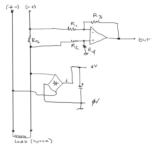
Hi, my problem is this; i need to measure current over DC circuit where the DC power polarity is casual. It is assimilable to the AC circuit and the shunt resistor go one time on the high side and one time in the low side. So, i have one shunt resistor of 0,6ohm value and the maximum power voltage of DC circuit is 12V. Because i need to power my measurement circuit with power over measured circuit, the Common mode voltage go one time to 0V and next time to 8/9V respect to ground. My question is: what is the best way to make the shunt reading floating respect the ground?

I try to explain with a drawing.

Thank's

Neri T.


TLV4113 - Power Save Mode Question

$
0
0

Hello Team,

I have a brief question regarding the TLV4113:

  • When the pins are biased such that Vdd = 0V and shutdown = 0V, will the part be damaged if the negative input gets an approximately 1.5V and less than 2 mA signal? The part would only be in this condition for short periods of time.

Since the max ratings specify +/- Vdd on the input pins, I would think that over time this condition would damage the part, but I was hoping to receive some confirmation/clarification. 

Thanks in advance,

Daniel Lanzone

OPT101 dark current

$
0
0

Hi, I want to measure little amount of light power with the opt101. I tried the basic circuit like in datasheet with 9V on pin 1, ground connected on pins 3 and 8, 0.1uF decoupling capacitor on pin 1 and I shorted pins 4 and 5 together. It works, but instead of getting around 7.5mV of dark current, I get around 70mV when I measure in absence of light. I tried 0.01uF capacitor instead but same result. Also, I tried another chip but same result.

I don't mind having a 70mV offset but I just want to know if its normal and if I'm gonna get the right signal out of it.

Thank you

Offset voltage of OPA376-Q1

$
0
0

Hi,

I am getting a 2mV input offset voltage for OPA376-Q1. The common mode voltage is Vin+ =2.676V , Vin- =2.674V . I got the OPAMP samples from TI itself.

Also observing  a variation in the offset voltage with respect to input common mode voltage. Input offset voltage get reduced while reducing input common mode voltage. At 1V input common mode voltage , offset is  1mV.

The datasheet specifies a maximum input offset voltage of 25uV.

regards,

Manu Sudevan

Using a OPA2209 as a DC signal Amplifier

$
0
0

Hi, few months ago I bought some OP2209, I did it for the purpose of implemented as a DC signal Amplifier.

I chose it because have a single supply alimentation (in my application I need to use USB alimentation) and the other features that make it a great OpAmp.

In my country I can only find old models of OpAmp (741, lm324, lm358...) but I need the best results that may have.

I want to use the OPA2209 as a Non-Inverting Amplifier but I can´t find a circuit that can provide me a good behavior.

I read the SLOA076 but I don't understand which circuit I have to implement.

In the past I used the OP07 (as a non-inverting amplifier, gain 11, and works great) but now I need to feed the OpAmp with Single Supply (like USB, +5V an Gnd). I did the Non-interting amplifier configuration with resistors values 1kOhm and 10kOhm.

This one is my old configuration that works fine.


Thanks, I hope you can help to solve my situation.

Best Regards.

Troubleshooting OPA445 - 5Vpp noise on protoboard

$
0
0

Hi,

I am attempting to replace a LM741 op amp(low voltage rated) with a OPA445(high voltage rated) in a feedback circuit. The issue is that the OPA445 is producing a 5 Vpp signal when this circuit is on a protoboard, but the LM741 doesn't show this 5 Vpp noise. Both are powered with 12 Volts supply. What's really puzzling is that the breadboard the OPA445 doesn't show the 5 Vpp noise, it's only when it's on the protoboard when the 5 Vpp noise is present.

Is there any specific reason a circuit with a high voltage op amp would show a 5 Vpp noise signal on a protoboard, but not on a breadboard?

Thanks in advance for your replies.

Anik

OPA735 Inverting amplifier problem

$
0
0

Hi All,

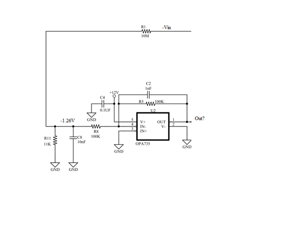
one of my power supply project am using OPA735 as unity gain inverting amplifier configuration with single supply (+12V)

my input to the inverting input is -1.27V max, and non inverting input is grounded, my question is in this case whether this will give inverted output of -1.27V or not?

please check attached schematic,

LM7321 Unity Gain

$
0
0

Hi,

I designed the LM7321 as a unity gain amp and got a reduced output of 15mV.

After 20 cascaded amps it is summed to 300mV.

How can I reduce it to not more than 2mV?

Thanks in advance.


OPA227 - Offset trimming

$
0
0

Hi all,

More a confirmation than a question... I do not intend to do any offset trimming once my OPA227 is on my PCB. I would like to confirm that both trimming pins (1 and 8) should be left unconnected... (I don't see any sort of schematics or instructions on the datasheets on what to do with this pins..).

If anyone can confirm that, that would make me happy ;)

Thanks.

OPA2188

$
0
0

Can OPA2188 be used as a comparator?

High Speed Current Sense

$
0
0

looking for high-speed precision current sense monitor like MAX9643. It has very large input common-mode voltage (from -1.5V to +60V); relative high slew rate (12V/µS) and signal bandwidth of 10MHz.


24V Battery operated system (INA114, XTR110) picking up noise

$
0
0

Reference circuit:  http://www.ti.com/lit/an/sboa025/sboa025.pdf

Hi,

I have the above circuit operating on 24V Battery. The only difference is that the load cell has a 3m long shielded cable.

Whenever there is any Mains operated switching in the vicinity, there is fluctuation of output current. Probing further, noise is observed on the power rails. Adding a filter before the INA114 and decoupling the power rails doesn't seem to help.

There is no earthing available as the unit is mounted on a mobile platform having rubber wheels. The load cell shield is terminated to DC Ground near the amplifier.

Can anyone help solve this problem?

Thanks,

JayantD

Need Simulation Spice model for LPV7215MF to be useded in Multisim 12

Viewing all 19430 articles
Browse latest View live


<script src="https://jsc.adskeeper.com/r/s/rssing.com.1596347.js" async> </script>